
Pressure spike reduction for refrigerant systems incorporating a microchannel heat exchanger

Active Publication Date: 2012-07-05
CARRIER CORP
View PDF9 Cites 39 Cited by
  • Summary
  • Abstract
  • Description
  • Claims
  • Application Information

AI Technical Summary

Benefits of technology

[0007]A refrigerant system includes at least one compressor that compresses refrigerant and delivers it downstream to a heat rejection heat exchanger. The heat rejection heat exchanger is a microchannel heat exchanger. Refrigerant passes from the heat rejection heat exchanger downstream to an expan

Problems solved by technology

However, there are also challenges associated with microchannel heat exchangers related to their small hydraulic diameter and substantial reduction in internal volume as compared to the conventional type of heat exchangers.
One challenge is that a microchannel condenser or gas cooler is susceptible to pressure spikes at start-up or other transient conditions, such as operational regime changes.
When pressure spikes occur in such a refrigerant system, they can lead to nuisance shutdowns and eventually to an inability to control environmental parameters, such as temperature and humidity, in the space to be conditioned.

Method used


Image

  • Pressure spike reduction for refrigerant systems incorporating a microchannel heat exchanger
  • Pressure spike reduction for refrigerant systems incorporating a microchannel heat exchanger
  • Pressure spike reduction for refrigerant systems incorporating a microchannel heat exchanger

Examples


Embodiment Construction

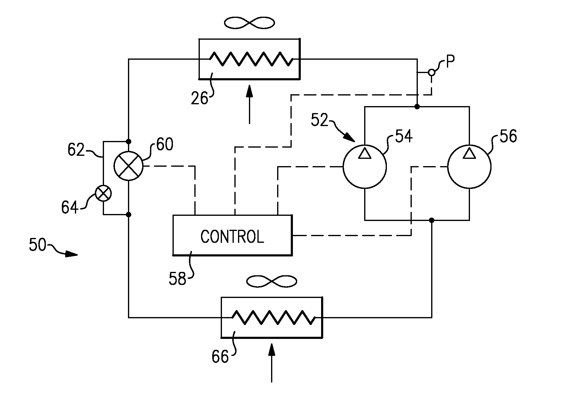
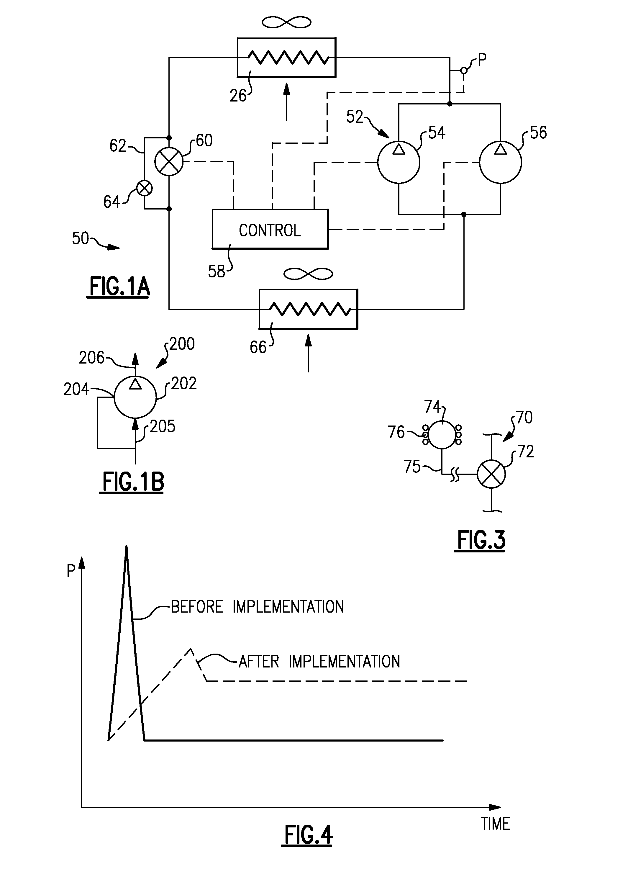
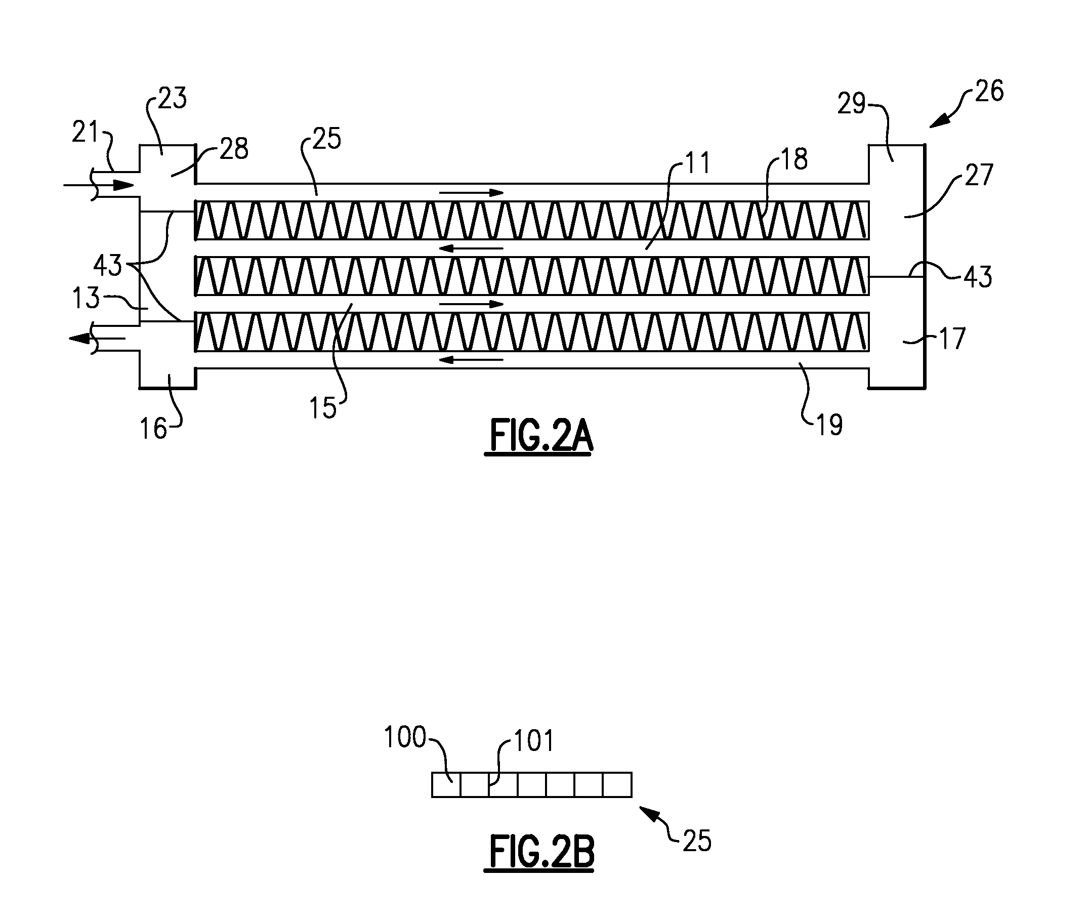
[0015]A refrigerant system 50 is illustrated in FIG. 1A incorporating a compressor bank 52 that is shown having tandem compressors 54 and 56. It should be understood that the refrigerant system 50 shown in FIG. 1 is the basic refrigerant system, and the refrigerant systems incorporating various options and features, known to a person skilled in the art, will equally benefit from the invention. Although tandem compressors are illustrated, a refrigerant system having a single compressor would also come within the scope of this invention. Similarly, more than two tandem compressors can be employed. The compressors 54 and 56 may be compressors having the ability to operate at several speeds or may incorporate other means of unloading. Control 58 operates to control the compressors 54 and 56. As an example, both compressors could be a two-speed compressor, or a multi-speed compressor such as a compressor having an electronically controlled motor which may be powered and controlled by pul...


PUM


Abstract

A refrigerant system includes at least one compressor (54, 56) that compresses refrigerant and delivers it downstream to a heat rejection heat exchanger (26). The heat rejection heat exchanger is a microchannel heat exchanger. Refrigerant passes from the heat rejection heat exchanger downstream to an expansion device (60), from the expansion device through an evaporator (66), and from the evaporator back to the at least one compressor. A control (58) operates at least one compressor and the expansion device to reduce pressure spikes at transient conditions.

Description

RELATED APPLICATION[0001]This application claims priority to U.S. Provisional Patent Application No. 61 / 257,586, which was filed Nov. 3, 2009.BACKGROUND OF THE INVENTION[0002]The disclosed invention relates to a control that is operable at transient conditions to reduce pressure spikes in a refrigerant circuit incorporating a microchannel heat exchanger. In particular, the disclosed invention relates to a control that is operable at transient conditions to reduce pressure spikes in a refrigerant circuit incorporating a microchannel condenser or gas cooler.[0003]In recent years, much interest and design effort has been focused on efficient and durable operation of the heat exchangers in refrigerant systems. One relatively recent advancement in heat exchanger technology is the development and application of parallel flow, or so-called microchannel or minichannel, heat exchangers (these terms will be used interchangeably throughout the text), as the indoor and / or outdoor heat exchanger...

Claims


Application Information

Patent Timeline
IPC IPC(8): F25B49/02F25B1/10F25B49/00F25B1/00
CPCF25B49/02F25B2341/0681F25B2400/0411F25B2400/075F25B2500/07Y02B30/741F25B2600/0253F25B2600/026F25B2600/2513F25B2700/1931F25B2500/26Y02B30/70
Inventor TARAS, MICHAEL F.LIFSON, ALEXANDER
Owner CARRIER CORP
Learn More