Bop control system circuit to reduce hydraulic flow/water hammer

a control system and hydraulic technology, applied in the direction of earth-moving drilling, sealing/packing, wellbore/well accessories, etc., can solve the problems of large force needed to drive the bop ram, large change in fluid velocity at the ram, and significant damage to the components of the bop. , to achieve the effect of reducing water hammer and reducing pressure spikes

Active Publication Date: 2016-08-04
HYDRIL USA DISTRIBUTION LLC
View PDF4 Cites 2 Cited by
  • Summary
  • Abstract
  • Description
  • Claims
  • Application Information

AI Technical Summary

Benefits of technology

[0009]One embodiment of the present technology provides a subsea blowout preventer (BOP) hydraulic control system to reduce water hammer. The system includes a first hydraulic fluid source, a first fluid supply conduit in fluid communication with the first hydraulic fluid source at an upstream end, and with a BOP function at a downstream end, and a first supply valve in the first fluid supply conduit that controls the amount of fluid flow through the first fluid supply conduit to the BOP function, the first supply valve having an open state and a closed state. The first supply valve includes a first choke that controls movement of the first supply valve between the open state and the closed state and vice versa so that such movement is retarded when the first supply valve state approaches the fully open or the fully closed state to reduce pressure spikes in the fluid of the first fluid supply conduit.

Problems solved by technology

The forces needed to drive the BOP rams can be large, as the equipment is heavy, and much force may be required to shear the steel drill string and other components in the bore.
Accordingly, when the supply valve opens to allow fluid flow to drive the rams, the change in velocity of fluid at the rams can be large and sudden.
Water hammer can cause significant damage to components on the BOP.

Method used


Image

  • Bop control system circuit to reduce hydraulic flow/water hammer
  • Bop control system circuit to reduce hydraulic flow/water hammer
  • Bop control system circuit to reduce hydraulic flow/water hammer

Examples


Embodiment Construction

[0021]The foregoing aspects, features, and advantages of the present technology can be further appreciated when considered with reference to the following description of preferred embodiments and accompanying drawings, wherein like reference numerals represent like elements. The following is directed to various exemplary embodiments of the disclosure. The embodiments disclosed should not be interpreted, or otherwise used, as limiting the scope of the disclosure, including the claims. In addition, those having ordinary skill in the art can appreciate that the following description has broad application, and the discussion of any embodiment is meant only to be exemplary of that embodiment, and not intended to suggest that the scope of the disclosure, including the claims, is limited to that embodiment.

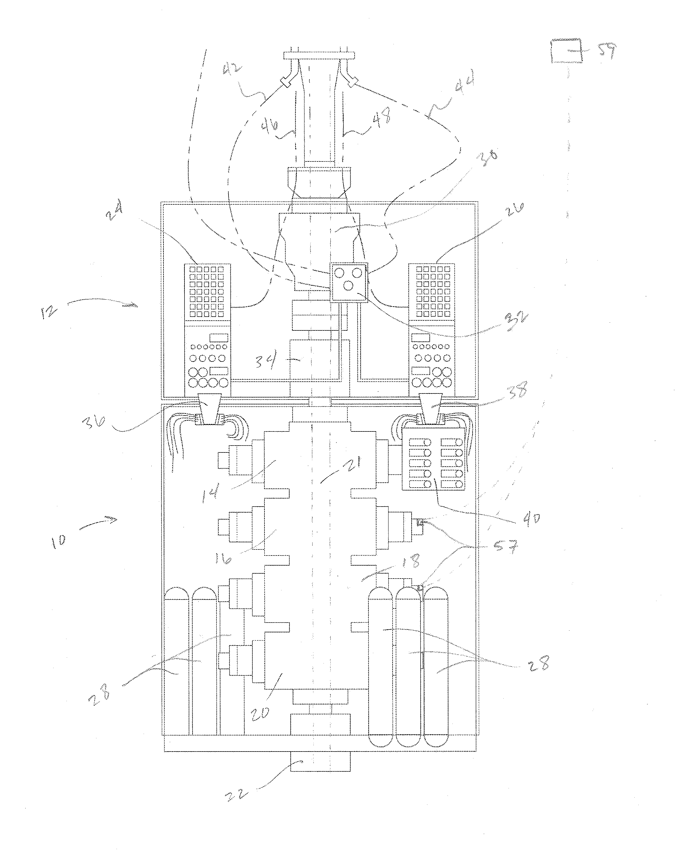
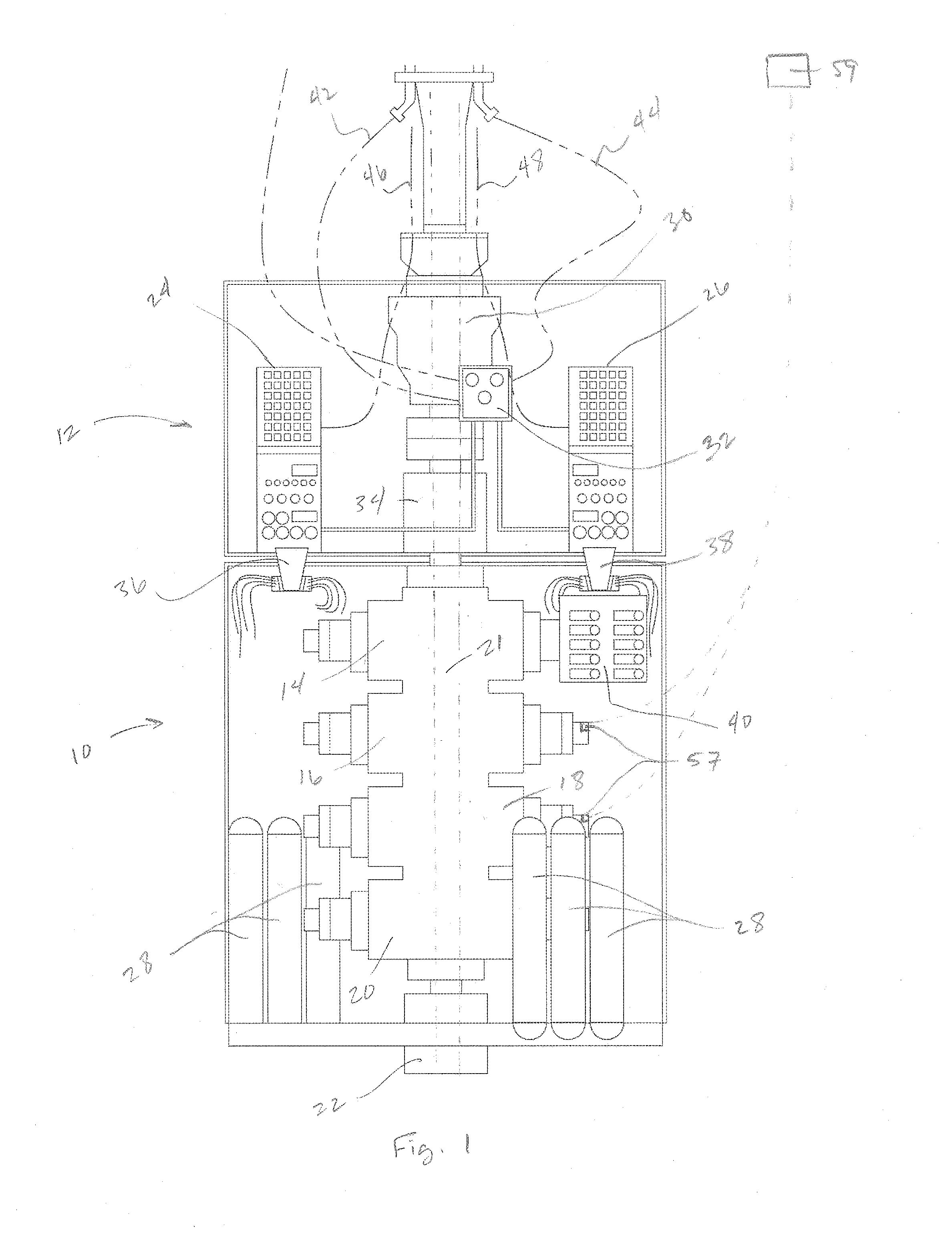
[0022]FIG. 1 shows a subsea blow out preventer (BOP) assembly, including a lower stack 10 and a lower marine riser package (LMRP) 12. Typically, the lower stack includes a series of stac...


PUM


Abstract

A subsea blowout preventer (BOP) hydraulic control system to reduce water hammer that includes a hydraulic fluid source. The system further includes a fluid supply conduit in fluid communication with the hydraulic fluid source at an upstream end, and with a BOP function at a downstream end. The system further includes a supply valve in the fluid supply conduit that controls the amount of fluid flow through the fluid supply conduit to the BOP function, the supply valve having an open state and a closed state. The supply valve has a choke that controls movement of the supply valve between the open state and the closed state and vice versa so that such movement is retarded when the supply valve state approaches the fully open or the fully closed state to reduce pressure spikes in the fluid of the fluid supply conduit.

Description

CROSS-REFERENCE TO RELATED APPLICATIONS[0001]This application claims priority to U.S. Provisional Patent Appln. No. 62 / 110242, which was filed on Jan. 30, 2015, the full disclosure of which is hereby incorporated herein by reference in its entirety.BACKGROUND OF THE INVENTION[0002]1. Technical Field[0003]Embodiments of the subject matter disclosed herein generally relate to subsea oil and gas drilling equipment. More particularly, the present technology relates to accumulator valves for use in subsea oil and gas drilling hydraulic circuits.[0004]2. Discussion of the Background[0005]Blowout preventers (BOPS) are important safety components in subsea well drilling operations. Typically, a BOP is attached to a wellhead at the sea floor, and provides a bore through which the drill string can pass from the top of the BOP down through the bottom and into the well. The BOP is equipped with BOP rams, which are located on opposing sides of the bore and are designed to close across the bore i...

Claims


Application Information

Patent Timeline
Patent Type & Authority Applications(United States)
IPC IPC(8): E21B33/035E21B33/064E21B33/06
CPCE21B33/062E21B33/064E21B34/16E21B33/06E21B33/0355
Inventor GUSTAFSON, RYAN CHEANEY
Owner HYDRIL USA DISTRIBUTION LLC
Why Eureka
Try Eureka