Dampening mechanisms for compound applicator

Inactive Publication Date: 2017-04-06
INGERSOLL PROD
View PDF6 Cites 0 Cited by
  • Summary
  • Abstract
  • Description
  • Claims
  • Application Information

AI Technical Summary

Benefits of technology

[0016]Preferably wherein the dampening means includes a resiliently deformable diaphragm with one side exposed to atmosphere and the other side expo

Problems solved by technology

These pressure fluctuations translate into variations in the quantity of material which is being ejected out of the end of the compound

Method used


Image

  • Dampening mechanisms for compound applicator
  • Dampening mechanisms for compound applicator
  • Dampening mechanisms for compound applicator

Examples


further embodiment

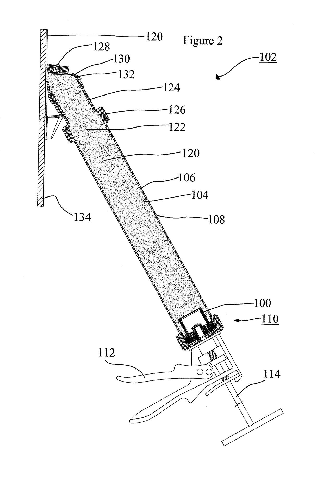
[0072]An alternate embodiment of the present concept, damping mechanisms for compound applicators, is shown as a sub-component of a compound applicator 400 in FIGS. 9 to 10.

[0073]Referring to FIGS. 8 to 11, the major components of compound applicator 400 are as follows: applicator head 402 attached to a tube reservoir 106 which in turns is attached to an applicator gun 501.

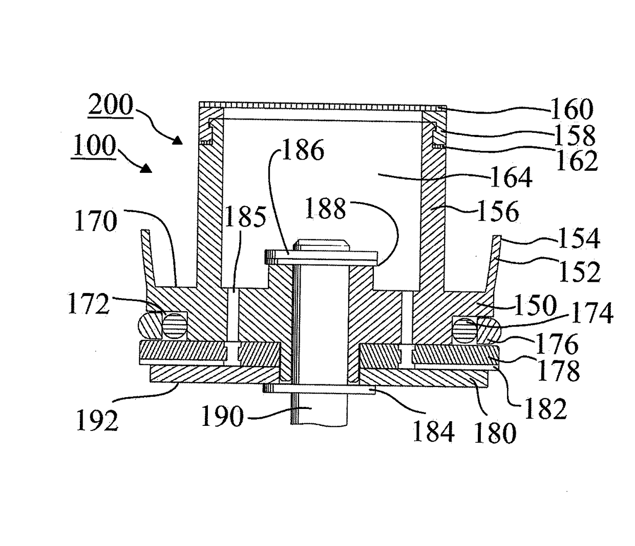
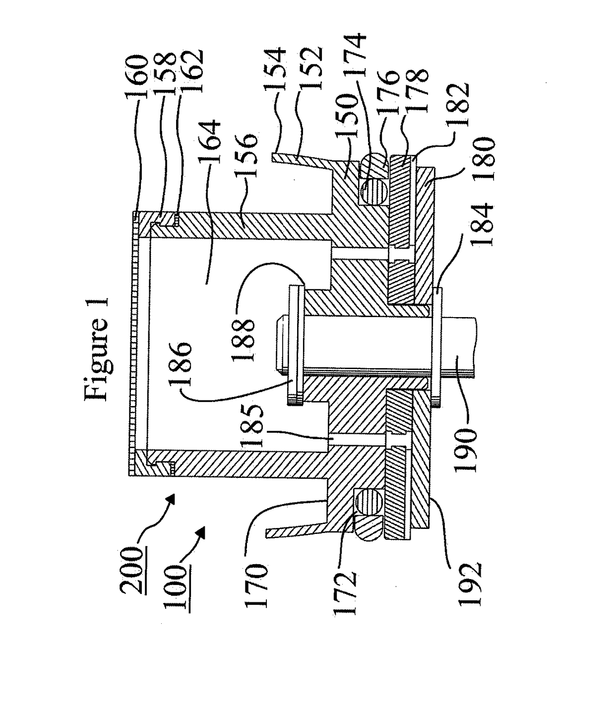
[0074]Referring now to FIGS. 8 to 10 the applicator head is depicted and shown generally as 402. The major components of the applicator head 402 are as follows: pressure control connector 404, body 406, front skid 408, and adjustment mechanism 110.

[0075]Pressure control connector 404 includes a means for dampening pressure spikes created in the tube reservoir 106 comprising: a hollow junction 410, one or more diaphragms 412 and one or more support inserts 414. The hollow junction 410 having a transverse section 416, a longitudinal section 418 and an outlet 420. The outlet 420 communicates with flow channel 656 sho...


PUM


Abstract

A dampening mechanism in combination with a compound applicator. The combination includes a compound applicator which further includes an incrementally iterative advancement mechanism for urging a plunger along a tube reservoir in preselected incremental strokes. The plunger urges compound along the tube reservoir and out through an applicator head. The compound applicator includes a device for dampening pressure spikes created in the tube reservoir during an incremental stroke of the plunger.

Description

[0001]The present application is a national stage entry of international application PCT / CA2015 / 000408 which claims priority from regularly filed U.S. provisional patent application 62 / 016,848 filed Jun. 25, 2014 under the title; PLUNGER FOR COMPOUND APPLICATOR in the name of Jamie Pentland.FIELD OF THE INVENTION[0002]The present concept relates to compound applicators and more particularly relates to dampening mechanisms used in compound applicators.BACKGROUND OF THE INVENTION[0003]Manual compound applicators normally utilize a trigger actuated advancement mechanism which pushes a push rod down a tubular reservoir which moves a plunger along the inside diameter of the tubular reservoir which in turn urges the compound housed within the tubular reservoir out through an exit end of the compound applicator.[0004]By its very nature the advancement mechanism which is manually actuated creates pressure spikes within the tubular reservoir wherein the pressure is greatest when the trigger ...

Claims


Application Information

Patent Timeline
IPC IPC(8): E04F21/165F16F9/04B05C17/01E04F21/08
CPCE04F21/1652E04F21/08B05C5/0262B05C17/0123F16F9/04E04F21/165
Inventor PENTLAND, JAMIE
Owner INGERSOLL PROD
Why Eureka
Try Eureka