
Entrapment tunnel monohull optimized for waterjet and high payload

Inactive Publication Date: 2007-09-20
NAVATEK
View PDF47 Cites 14 Cited by
  • Summary
  • Abstract
  • Description
  • Claims
  • Application Information

AI Technical Summary

Benefits of technology

[0015]Another object of the present invention is that the amas have bow shapes developed to provide effective and efficient flow along the hull as the craft is propelled through the water.
[0018]Yet another object of the present invention is that at operating speeds the aft areas of the tunnels will remain wetted in operation although dynamic lift and trim effects may ventilate the forward portion of those tunnels.
[0020]It is a further object of the invention that the shape of the tunnels reduces or prevents the entrainment of air turbulence beneath the main hull.

Problems solved by technology

Either submerged propellers or waterjets lose efficiency and effectiveness when ventilated and this has been a serious problem with prior art craft of the type described above.
The angular shape does not vent excessive amounts of entrapped tunnel fluid that a flat or arcuate tunnel would which could result in less effective tunnel lift at higher speeds.

Method used


Image

  • Entrapment tunnel monohull optimized for waterjet and high payload
  • Entrapment tunnel monohull optimized for waterjet and high payload
  • Entrapment tunnel monohull optimized for waterjet and high payload

Examples


Embodiment Construction

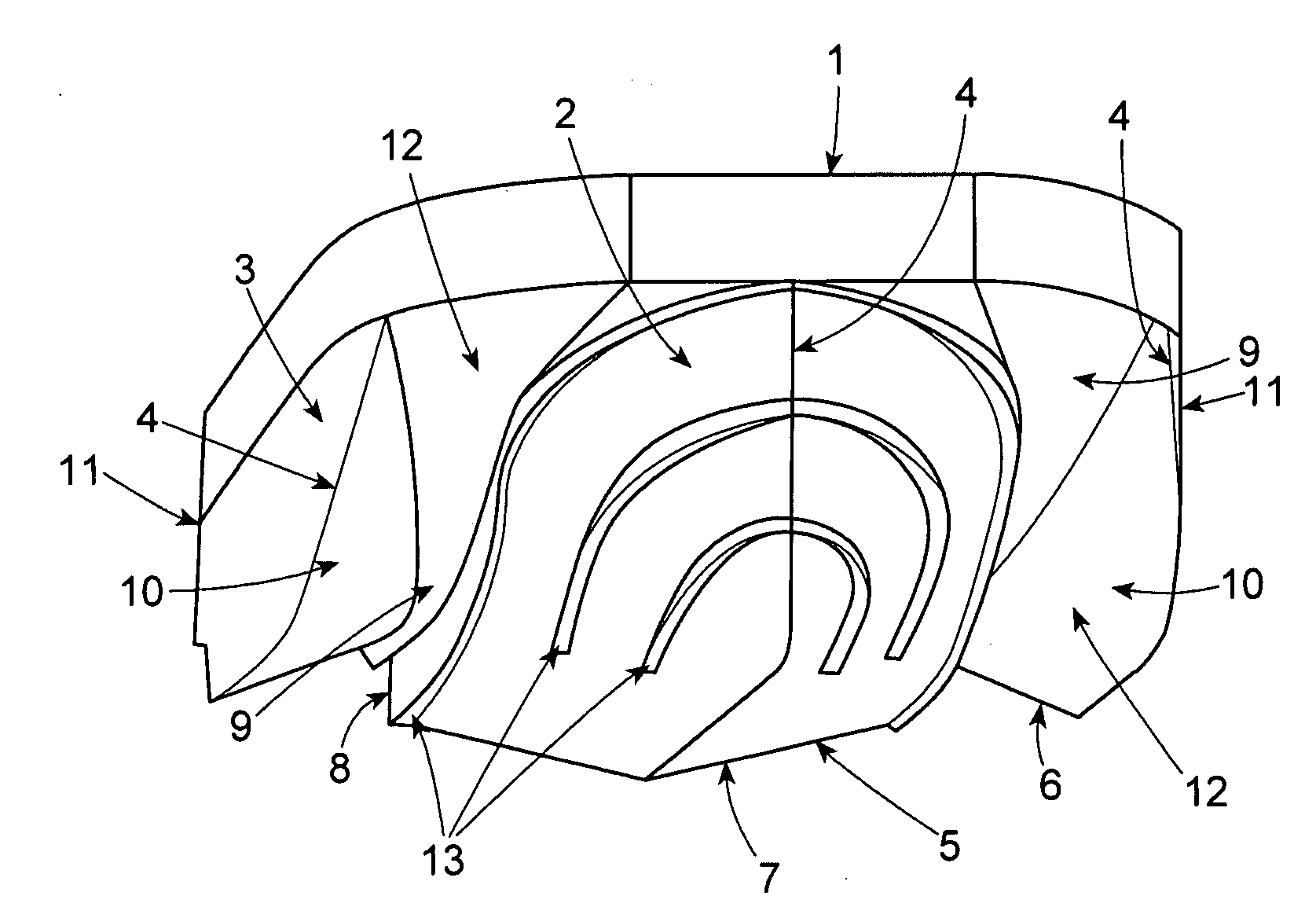
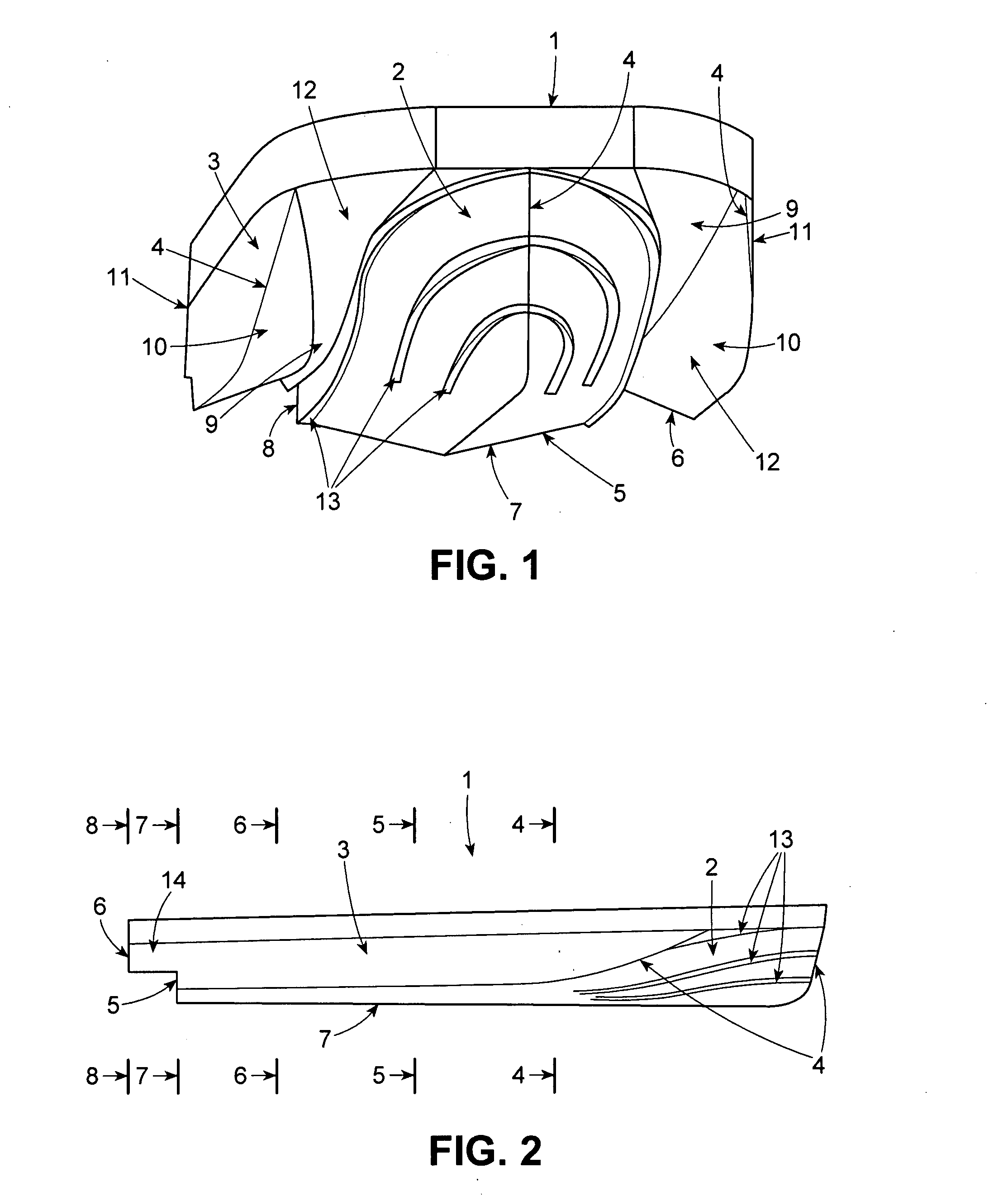
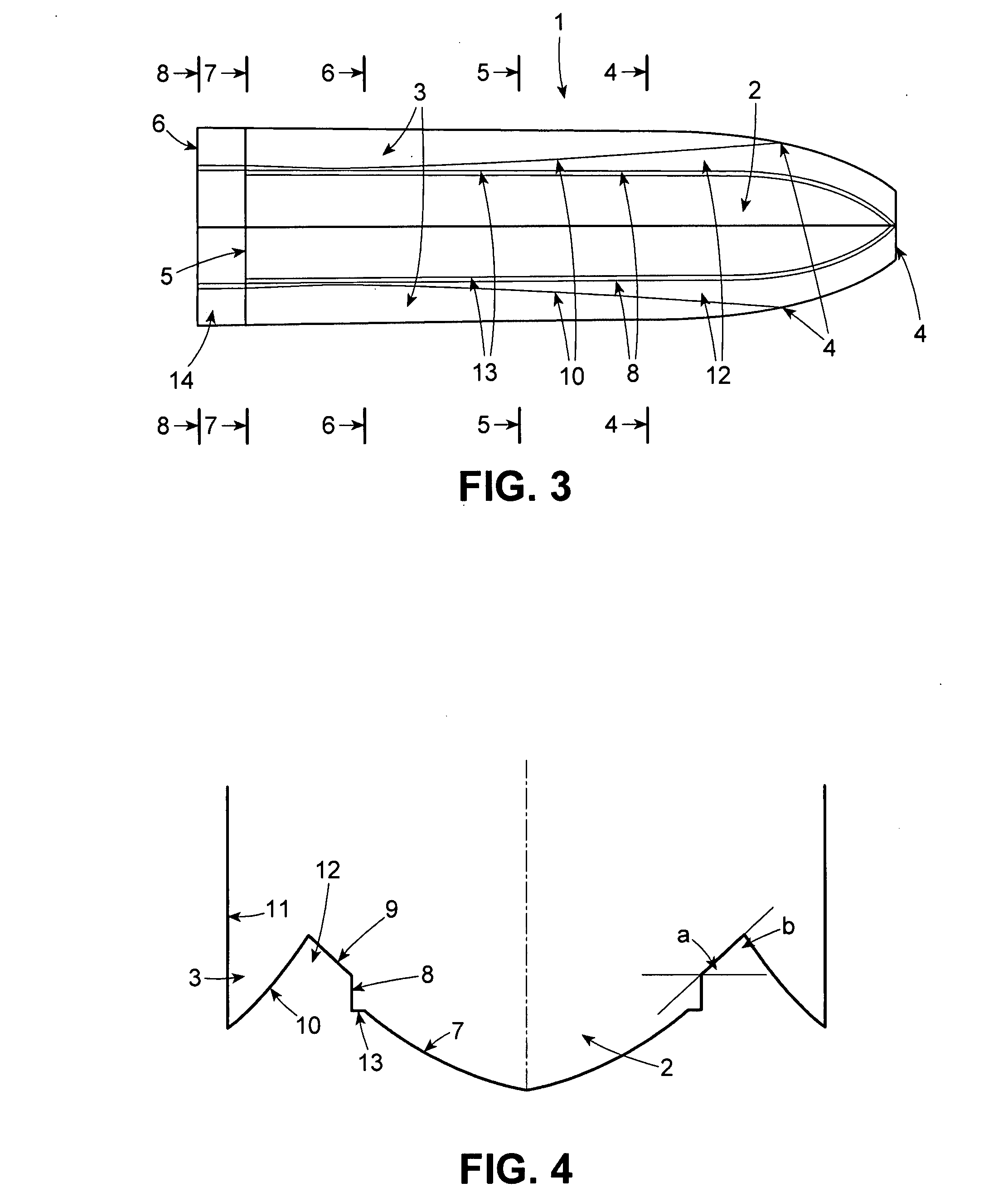
[0034]Referring now to the drawings in detail, and initially to FIG. 1, a watercraft vessel 1 constructed in accordance with the present invention is shown which has a main central hull 2, and two outboard amas 3. Main hull 2 and amas 3 each have a bow 4, transoms 5 and 6, respectively (FIGS. 8, 11).

[0035]The main hull 2 also has a bottom 7 and sides 8.

[0036]Amas 3 each have an inboard surface 10 and outboard side 11. The stability of the watercraft is developed through the length, outboard placement and sizing of the amas. Main hull running bottom 7 provides the primary buoyancy and planing lift to the craft with its variable deadrise and fineness ratio balancing the required usable craft beam, seakeeping, efficiency and lift. The preferred configuration is variable deadrise to allow greater hull loading. The amount of deadrise and its variability is a function of the amount of hull loading required which determines the weight carrying ability of the craft. A monohedron or constant...


PUM


Abstract

An entrapment tunnel watercraft vessel having three hulls consists of a main hull and two amas arranged outboard of the main hull with the keels of the three hulls being parallel. The main hull is a narrow, vee hull with variable, rearwardly decreasing deadrise. The amas have very fine bows and narrow, asymmetric deep-V hulls, with nearly vertical slab outboard sides above their keels and variable reverse deadrise on their inboard sides with the reverse deadrise angles decreasing from bow to stem. The tunnels on each side of the main hull are formed by three distinct surfaces, the sides of the main hull above its chine, the reverse deadrise inboard sides of each ama upward from their keels and a ceiling surface transversely spanning the aforementioned sides and having rearwardly increasing deadrise and rearwardly decreasing width. The tunnel ceilings slopes down from the bow to a section aft of midship where the ceiling height above the keel remains essentially constant. At speed the craft generates substantial amounts of lift and positive trim, thereby reducing the forward wetted length of the immersed tunnel ceiling and the apex of the ceiling is approximately at the craft dynamic waterline. As a result the watercraft vessel has improved seakeeping, stability and weight carrying ability.

Description

[0001]This application is based on U.S. Provisional Application No. 60 / 782,278 filed Mar. 15, 2006.TECHNICAL FIELD [0002]The present invention relates to a watercraft, and more particularly to an engine-powered craft having three parallel hulls with the center of the said three hulls being of a vee form having varying deadrise depending on the purpose of the craft, and two outer hulls, i.e., the amas having considerably greater reverse deadrise facing the deadrise of the center hull and essentially vertical outboard surfaces.BACKGROUND OF THE INVENTION[0003]Prior art air entrapment tunnel boats including catamarans, air entrapment tunnel monohulls, etc. are designed for the tunnel ceilings to become totally ventilated at design speeds and thereby reduce wetted surface drag while achieving some aerodynamic lift.[0004]Other prior art watercraft, as for example, the Hickman Sea Sled, Boston Whalers, Tri-hulls and cathedral hulls are designed to keep aft portions of their entrapment tun...

Claims


Application Information

Patent Timeline
IPC IPC(8): B63B1/32
CPCB63B1/20B63B1/38Y02T70/122B63B2001/208B63B2001/201B63B2001/005B63B2001/186Y02T70/10
Inventor CAMPBELL, LORNE FREDERICK
Owner NAVATEK
Learn More