

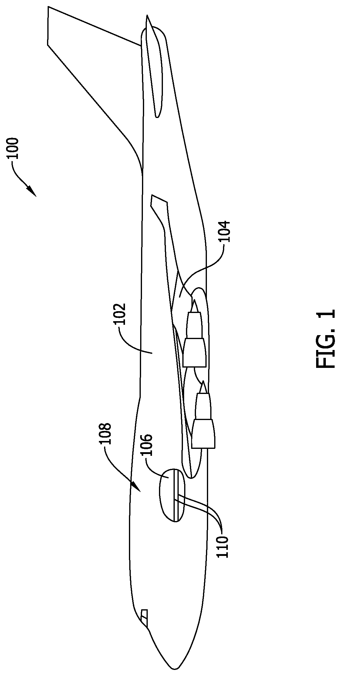
System and method for a helical pressure snubber
a technology of helical pressure and snubber, which is applied in the field of fluid flow systems, can solve problems such as transient pressure spikes within the system, and achieve the effect of reducing pressure spikes of the flow and reducing pressure spikes in the transducer
- Summary
- Abstract
- Description
- Claims
- Application Information
AI Technical Summary
Benefits of technology
Problems solved by technology
Method used
Image

Examples
Embodiment Construction
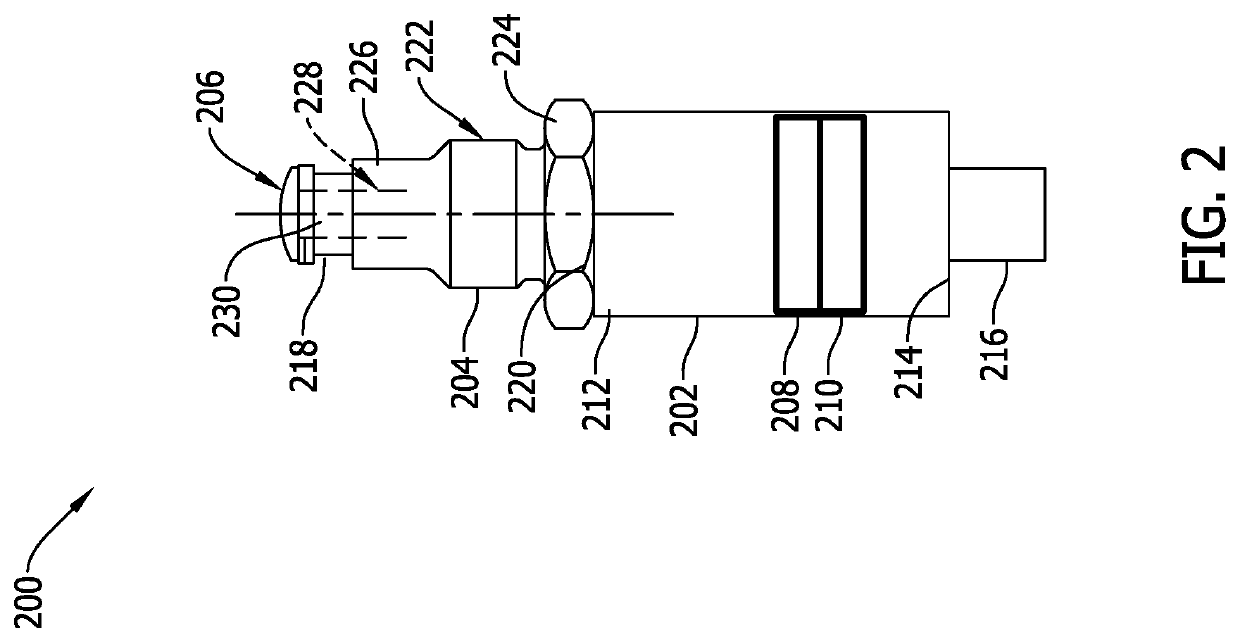
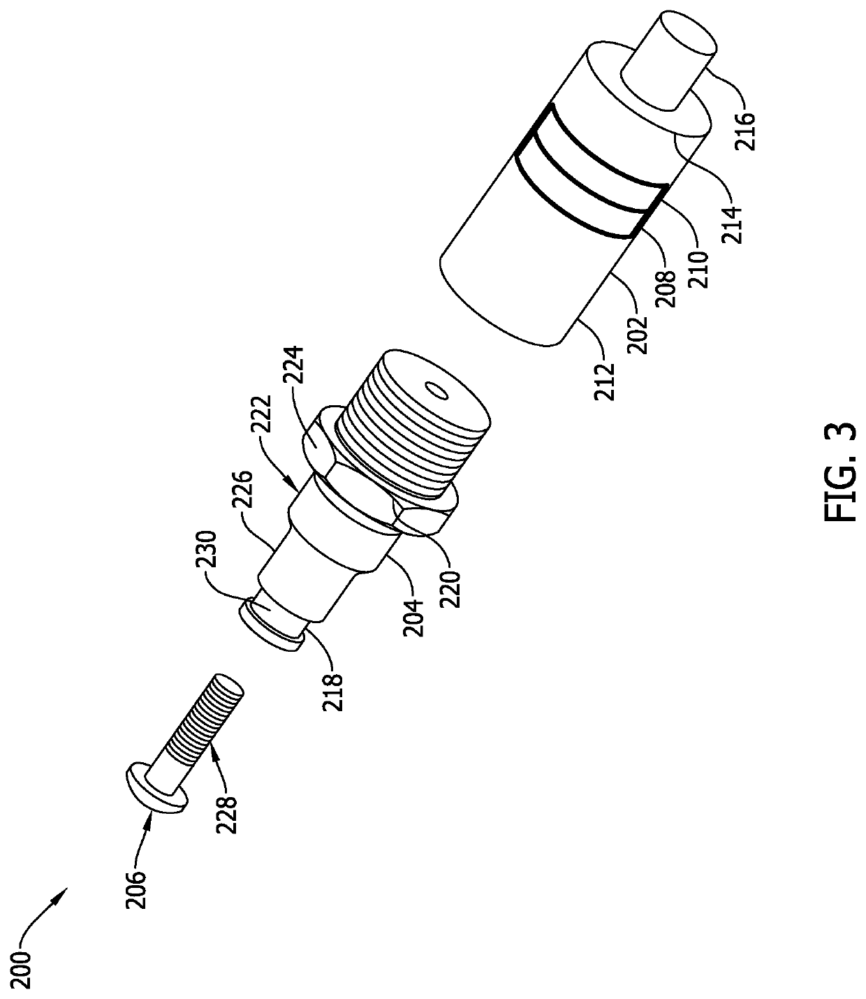
[0025]Embodiments of the systems and methods described herein include a pressure sensor including a snubber configured to reduce transient pressure spikes detected by the pressure sensor. Specifically, the pressure sensor also includes a transducer and a fitting coupled to the transducer. The fitting defines a threaded conduit configured to channel a fluid to the transducer. The snubber includes a head portion and a threaded portion. The threaded portion and the threaded conduit define at least one fluid flow path when the snubber is installed in the fitting. The fluid flow paths are substantially smaller than the threaded conduit and have a substantially higher pressure drop than the threaded conduit. Accordingly, the fluid flow paths substantially reduce transient pressure spikes within the transducer and allows the transducer to accurately measure the steady state pressure of the fluid system. As such, the snubber protects the transducer by reducing transient pressure spikes meas...
PUM
| Property | Measurement | Unit |
|---|---|---|
| diameter | aaaaa | aaaaa |
| pressure | aaaaa | aaaaa |
| transient pressure | aaaaa | aaaaa |
Abstract
Description
Claims
Application Information