System for combined cycle mechanical drive in cryogenic liquefaction processes

a technology of combined cycle and mechanical drive, which is applied in the direction of refrigeration and liquifaction, lighting and heating equipment, solidification, etc., to achieve the effect of low fuel demand and low operating cos

Inactive Publication Date: 2011-09-01
HAMWORTHY OIL & GAS SYST AS
View PDF7 Cites 34 Cited by
  • Summary
  • Abstract
  • Description
  • Claims
  • Application Information

AI Technical Summary

Benefits of technology

[0010]The low temperature or sub-cooling loop is physically placed on the gas turbine driven unit and the high temperature or de-superheating loop is preferably physically situated on the steam turbine driven unit. The medium temperature or condensation and cooling loop is typically split between the two. Since the level of generated power between the steam...

Problems solved by technology

However, even though the traditional Brayton process did not perform as well in terms of liquefaction power as cascade processes, mixed refrigerant processes and other large scale liqu...

Method used


Image

  • System for combined cycle mechanical drive in cryogenic liquefaction processes
  • System for combined cycle mechanical drive in cryogenic liquefaction processes
  • System for combined cycle mechanical drive in cryogenic liquefaction processes

Examples


Embodiment Construction

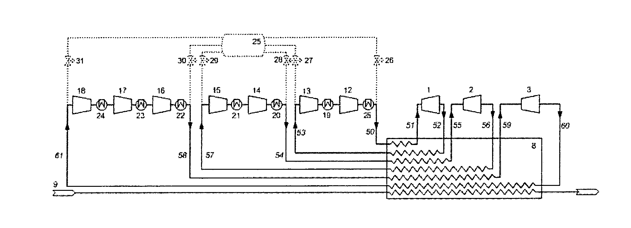
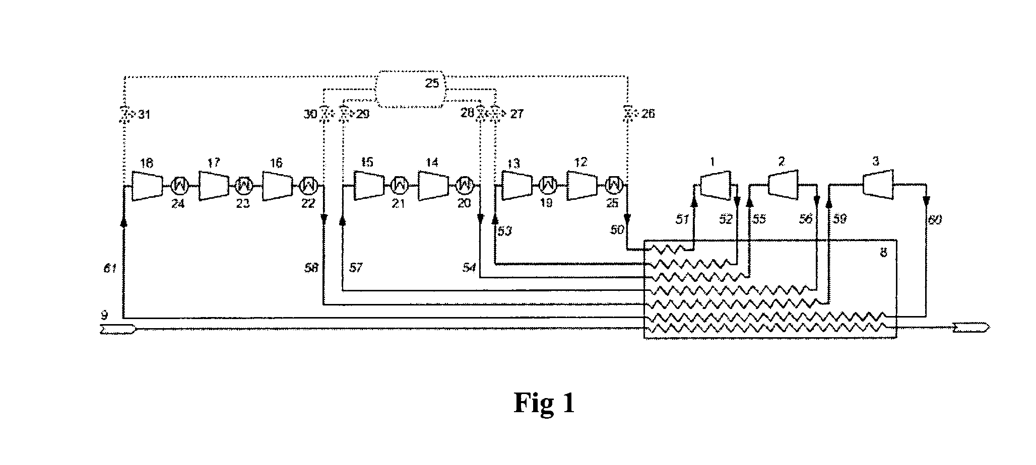
[0014]As illustrated in FIG. 1, the present refrigeration assembly comprises three different refrigeration loops:[0015]a high temperature loop, here depicted with two compressors 12, 13 or compressor stages and one expander 1 or expander stage, hereinafter only denoted compressors and expanders, respectively. As for all three loops this is a base case, but if the process advantages are obvious, this lay out may consist of a different number of compressor or expander units, depending process requirements or other criteria. The high temperature loop is used for de-superheating;[0016]a medium temperature loop is used to condense the LNG, and this loop normally consists of two compressors 14, 15 and one expander 2; and[0017]a low temperature loop consists of three compressors 16, 17, 18 and one expander in the base case also, and is used to sub-cool the LNG.

[0018]Further information for the refrigeration assembly is to be found in the Norwegian Patent Application 2008 3740 and the same ...


PUM


Abstract

A system for producing liquefied and sub-cooled natural gas by means of a refrigeration assembly using a single phase gaseous refrigerant comprises at least two expanders; a compressor assembly; a heat exchanger assembly for heat absorption from natural gas; and a heat rejection assembly, in which the expanders are arranged in expander loops and the refrigerant to the respective expander is served in a compressed flow by means of the compressor assembly having compressors or compressor stages enabling adapted inlet and outlet pressures for the respective expander. According to the present the expanders and compressors assembly are assembled in two mechanically connected compressor and expander packages of which one is driven by a gas turbine and the other is driven by a steam turbine, the steam primarily being generated by exhaust gases from the gas turbine in a waste heat recovery unit, and in that the expanders and compressors assemblies are distributed between the two compressor and expander packages to optimize the steam utilization and to balance the power generated by the gas turbine and the steam turbine.

Description

BACKGROUND OF THE INVENTION[0001]Different variations of the Brayton cooling cycle have been continuously developed and described in patent literature over the years. The nature of the first single expander systems could speak in favour of utilizing the process for cooling applications, rather than for liquefaction, due to the fact that the refrigerant remains in single phase throughout the cycle and therefore is easier adaptable to single phase loads like gas cooling, for instance.[0002]However, even though the traditional Brayton process did not perform as well in terms of liquefaction power as cascade processes, mixed refrigerant processes and other large scale liquefaction systems, the simplicity, robustness and flexibility of the process resulted in some popularity also for liquefaction purposes, e.g. for the production of liquefied natural gas (LNG). Especially for smaller plant the simple Brayton systems have proved to be feasible.[0003]When regarded for use in larger scale n...

Claims


Application Information

Patent Timeline
IPC IPC(8): F25J1/00
CPCF25J1/0022F25J1/005F25J1/0207F25J1/0242F25J1/0279F25J1/0282F25J2240/82F25J1/0288F25J1/0289F25J1/029F25J1/0298F25J2230/20F25J1/0283F25J2270/16
Inventor HORLYK, LARSHAUKEDAL, BJORN HARALD
Owner HAMWORTHY OIL & GAS SYST AS
Why Eureka
Try Eureka