Multi-core fiber and method of positioning of core of multi-core fiber

a multi-core fiber and positioning method technology, applied in the field of multi-core fibers, can solve the problems of multi-core fiber and difficult to increase the density of the core, and achieve the effect of reducing the difference in propagation characteristics and mitigating the increase of propagation characteristics

Inactive Publication Date: 2016-05-10
NAT UNIV CORP YOKOHAMA NAT UNIV
View PDF21 Cites 16 Cited by
  • Summary
  • Abstract
  • Description
  • Claims
  • Application Information

AI Technical Summary

Benefits of technology

[0105]As explained above, according to the present invention, in the multi-core fiber provided with multiple types of non-identical cores having different propagation constants, it is possible to reduce a difference in propagation characteristics between the non-identical cores.
[0106]In addition, when core density is increased by increasing the number of non-identical core types, expansion of a range of the gap between the relative refractive index differences Δ in the non-identical cores is controlled, thereby mitigating increase of the difference in propagation characteristics between the cores.

Problems solved by technology

An attempt to configure an uncoupled multicore fiber, by use of identical cores with the same propagation constant, requires to separate the cores significantly so as to avoid cross talk therebetween, and this makes it difficult to increase the core density.
The multi-core fiber has a problem of cross talk caused by coupling phenomenon, that is, signal light leaks mutually into the cores within the optical fiber.

Method used


Image

  • Multi-core fiber and method of positioning of core of multi-core fiber
  • Multi-core fiber and method of positioning of core of multi-core fiber
  • Multi-core fiber and method of positioning of core of multi-core fiber

Examples


Embodiment Construction

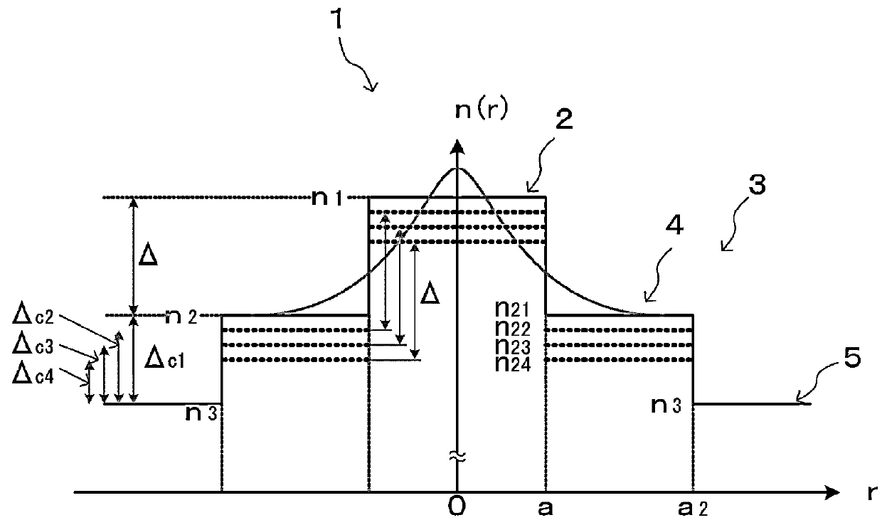
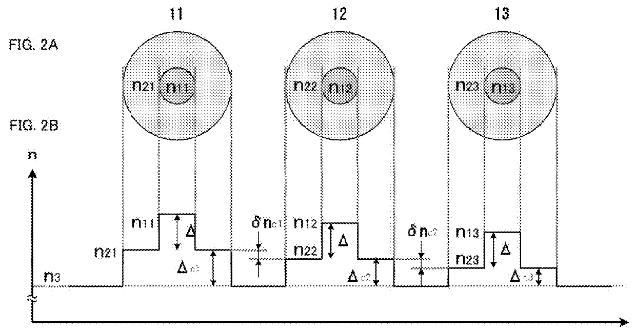
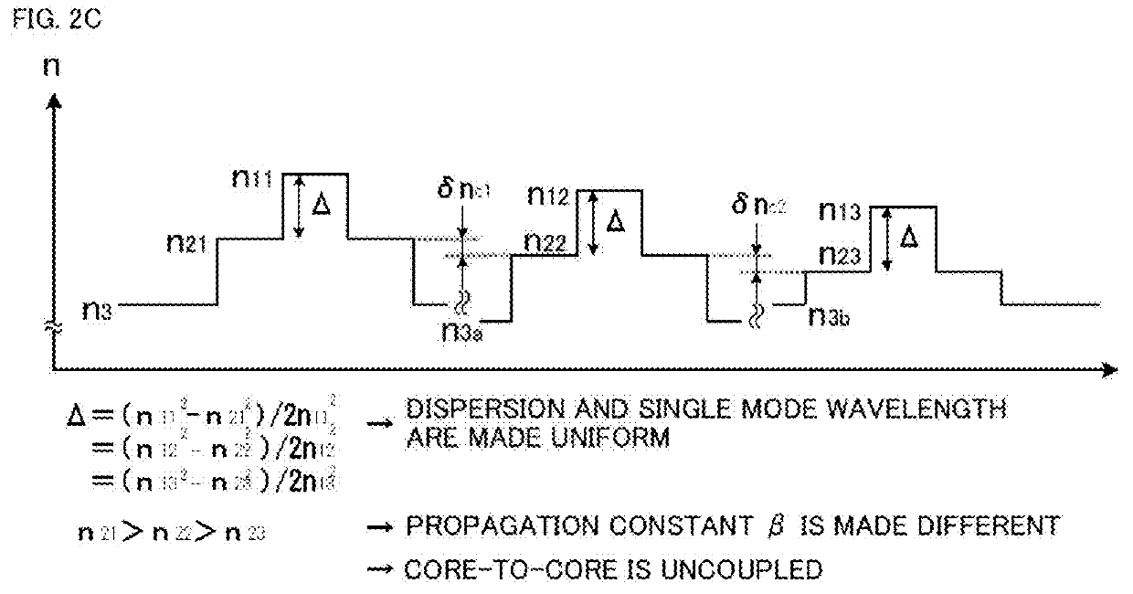
[0147]Hereinafter, with reference to the drawings, preferred embodiments of the present invention will be explained in detail. With reference to the figures from FIG. 1 to FIG. 23, a configuration of the multi-core fiber of the present invention will be explained, and with reference to the figures from FIG. 24 to FIG. 31, a core arrangement in the multi-core fiber of the present invention will be explained. FIG. 1 to FIG. 6 and FIG. 24 to FIG. 30 are figures for explaining the configuration example that is not provided with a low refractive index portion and an arrangement example of the non-identical cores. FIG. 7 to FIG. 23, and FIG. 31 are figures for explaining a configuration example that is provided with the low refractive index portion and an arrangement example of the non-identical cores.

[0148]The multi-core fiber of the present invention has a configuration for accommodating multiple single mode cores in one optical fiber, the core incorporating a core part and a cladding p...


PUM

PropertyMeasurementUnit
coupling length lcaaaaaaaaaa
diameteraaaaaaaaaa

Abstract

A multi-core fiber for accommodating multiple single mode cores in one optical fiber is provided with multiple types of non-identical cores having different propagation constants. Each of the multiple types of non-identical cores includes a core part and a cladding part covering an outer periphery of the core part. The cladding part has a double cladding structure including a first cladding for surrounding an outer periphery of the core part and a second cladding on the outer side of the first cladding. In the multiple types of non-identical cores, an optical electromagnetic profile in the core part and the first cladding is confined within a range of the core part and the first cladding, restricting a leakage thereof to the second cladding, and the propagation constant of each non-identical core is made different using the refractive index of the first cladding as a parameter.

Description

TECHNICAL FIELD[0001]The present invention relates to a multicore fiber for use in high-density space-division multiplexed transmission, and a method for arranging cores thereof.BACKGROUND ART[0002]As terms for representing a coupled state of signals between cores in a general sense, the term “coupled state” and the term “imperfect coupled state” are used. As terms for representing the inter-core coupled state in a strict sense, the term “perfect coupled state” and the term “uncoupled state” are known.[0003]The term “coupled state” represents a coupled state in which the coupling efficiency is almost 1, and the term “imperfect coupled state” represents a coupled state in which the coupling efficiency is smaller than 1 but not perfectly zero.[0004]The term “perfect coupled state” represents a coupled state in which the coupling efficiency is perfectly 1, and the term “uncoupled state” represents a coupled state in which the coupling efficiency is close to zero, being a value at which...

Claims


Application Information

Patent Timeline
Patent Type & Authority Patents(United States)
IPC IPC(8): G02B6/40G02B6/46G02B6/02G02B6/036
CPCG02B6/02042G02B6/03633G02B6/46Y10T29/49826
Inventor KOKUBUN, YASUOWATANABE, TATSUHIKO
Owner NAT UNIV CORP YOKOHAMA NAT UNIV
Why Eureka
Try Eureka