Electrical connector having a receptacle with a shielding plate and a mating plug with metallic side arms

a technology of electrical connectors and shielding plates, applied in the direction of printed circuit parts, coupling device connections, printed circuit non-printed electric components, etc., can solve the problems of waste of software switches or hardware switches, complicated sensing circuits,

Active Publication Date: 2016-05-24
FOXCONN INTERCONNECT TECH LTD
View PDF22 Cites 67 Cited by
  • Summary
  • Abstract
  • Description
  • Claims
  • Application Information

AI Technical Summary

Problems solved by technology

When the contacts are more, the sensing circuit is more complicated, which will waste software switches or hardware switches.

Method used


Image

  • Electrical connector having a receptacle with a shielding plate and a mating plug with metallic side arms
  • Electrical connector having a receptacle with a shielding plate and a mating plug with metallic side arms
  • Electrical connector having a receptacle with a shielding plate and a mating plug with metallic side arms

Examples


Embodiment Construction

[0031]Reference will now be made in detail to the preferred embodiment of the present invention.

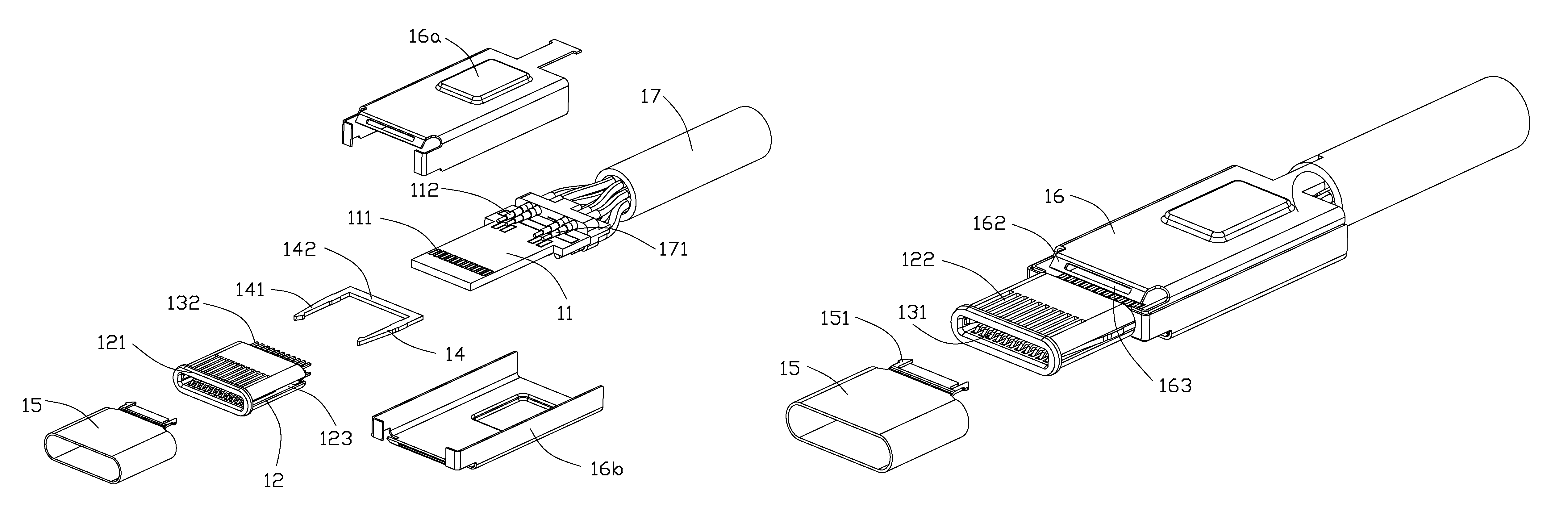
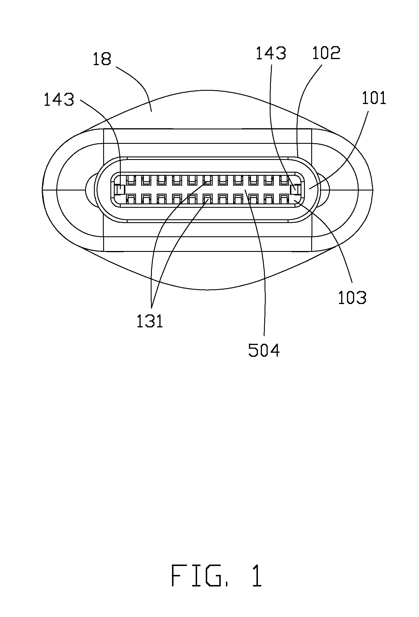
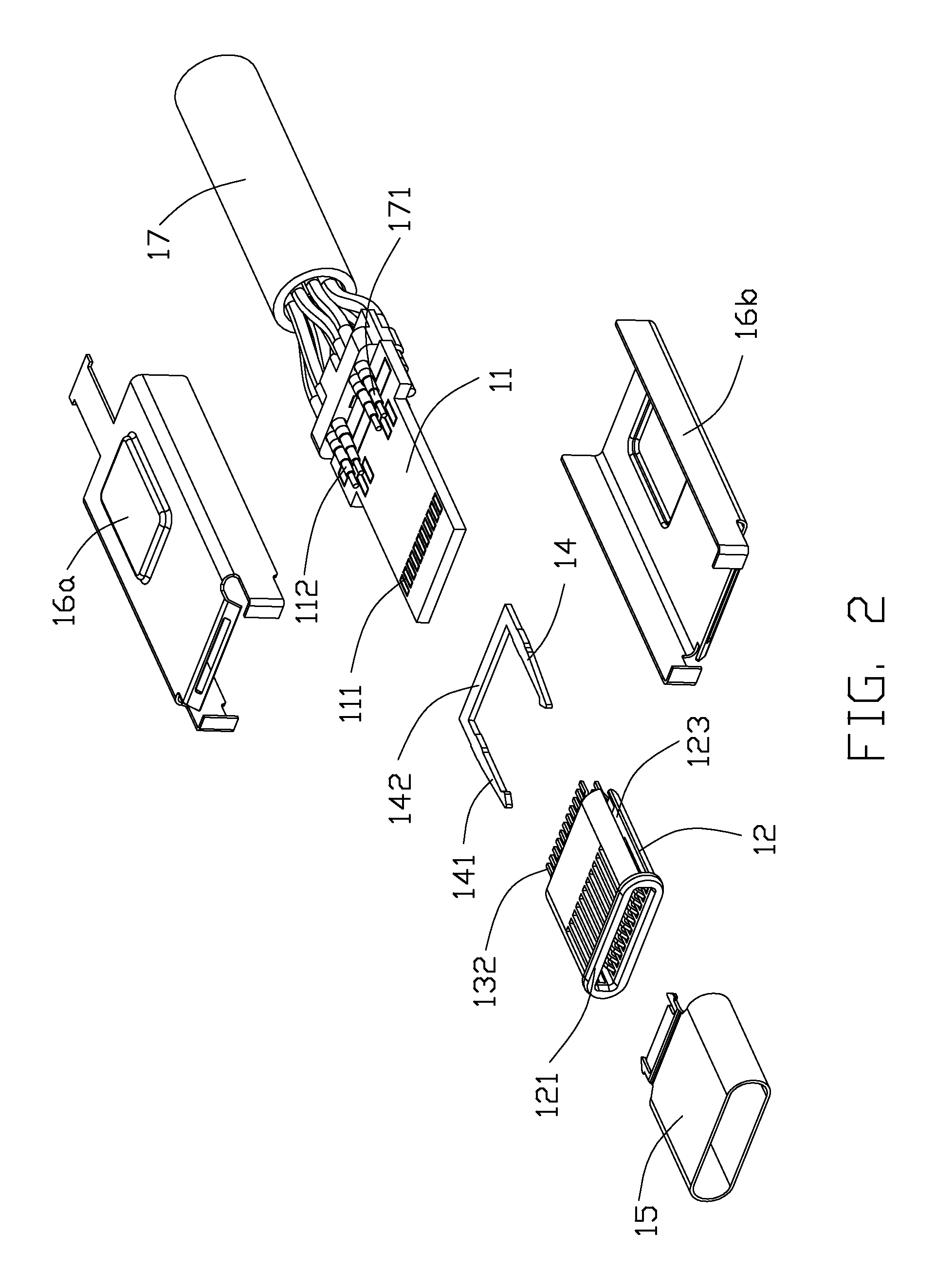
[0032]Referring to FIGS. 1-5, the instant invention discloses a first connector of a plug connector type 100 defines a front mating end 101 with a capsular configuration outlet 102 and a rectangular mating slot 103, which can be inserted into a second connector of a receptacle connector 200 mounted on a printed circuit board 900, either in either of two insertion orientations. The plug connector 100 includes a paddle card 11 with front circuit pads 111 and rear circuit pads 112 on two opposite surfaces of the paddle card 11. An insulative housing 12 located in front of the paddle card 11, is enclosed in a front metallic shell 15 in a seamless metallic sleeve type and defines the mating slot 103 between two walls 121 each equipped with a plurality of deflectable contacts 13 in the corresponding passageways 122, respectively, each having a front contacting section 131 extending into the mat...


PUM


Abstract

A plug connector includes an insulative housing with mating slot, contacts disposed in the housing by two sides of the mating slot, and a pair of side arms located by two opposite ends of the mating slot in a horizontal transverse direction. a receptacle connector includes an insulative housing defining a horizontal mating tongue; contacts disposed in the housing with contacting sections exposed upon two opposite surfaces of the mating tongue; and a monolithic horizontal metallic shielding plate disposed and extending substantially fully the mating tongue. The shielding plate defines side protruding edge sections exposed outside of corresponding side edges of the mating tongue and a notch structure on each side protruding edge section, the pair of side arms each defines a hook structure to engagement with the notch structure.

Description

CROSS REFERENCE TO RELATED APPLICATIONS[0001]This application is a continuation-in-part application of Ser. No. 14 / 477,889 filed Sep. 5, 2014, of Ser. No. 14 / 497,205 filed Sep. 25, 2014, and of Ser. No. 14 / 517,941 filed Oct. 20, 2014, and claims the benefit of, and priority to, U.S. Provisional Patent Application No. 61 / 917,363, filed Dec. 18, 2013, and Provisional Patent Application No. 61 / 926,270, filed Jan. 11, 2014, the contents of which are incorporated entirely herein by reference.BACKGROUND OF THE INVENTION[0002]1. Field of the Invention[0003]The present invention relates to an electrical connector, and more particularly to a flippable plug connector used with a receptacle connector.[0004]2. Description of Related Art[0005]US Patent Publication No. 20130095702A1 discloses a dual orientation plug connector, which has a connector tab with first and second major opposing sides and a plurality of electrical contacts carried by the connector tab. The plurality of contacts may incl...

Claims


Application Information

Patent Timeline
Patent Type & Authority Patents(United States)
IPC IPC(8): H01R24/60H01R13/66H01R13/6581H05K1/18H01R12/72H01R13/642H01R13/6582H01R24/28H05K1/11H01R107/00
CPCH01R24/60H01R13/6581H01R13/6658H01R12/724H01R13/642H01R13/6582H01R24/28H01R2107/00H05K1/117H05K1/184H05K2201/10189H01R13/6591H01R24/30
Inventor LITTLE, TERRANCE F.CHENG, CHIH-PIYANG, CHIH-KAI
Owner FOXCONN INTERCONNECT TECH LTD
Why Eureka
Try Eureka