
Motor vehicle with a vehicle frame

a vehicle frame and motor vehicle technology, applied in the direction of superstructure connections, suspension arms with pips, transportation and packaging, etc., can solve the problems of increased material costs and additional weight of components, and achieve the effect of high stability

Inactive Publication Date: 2016-05-31
ZF FRIEDRICHSHAFEN AG
View PDF32 Cites 1 Cited by
  • Summary
  • Abstract
  • Description
  • Claims
  • Application Information

AI Technical Summary

Benefits of technology

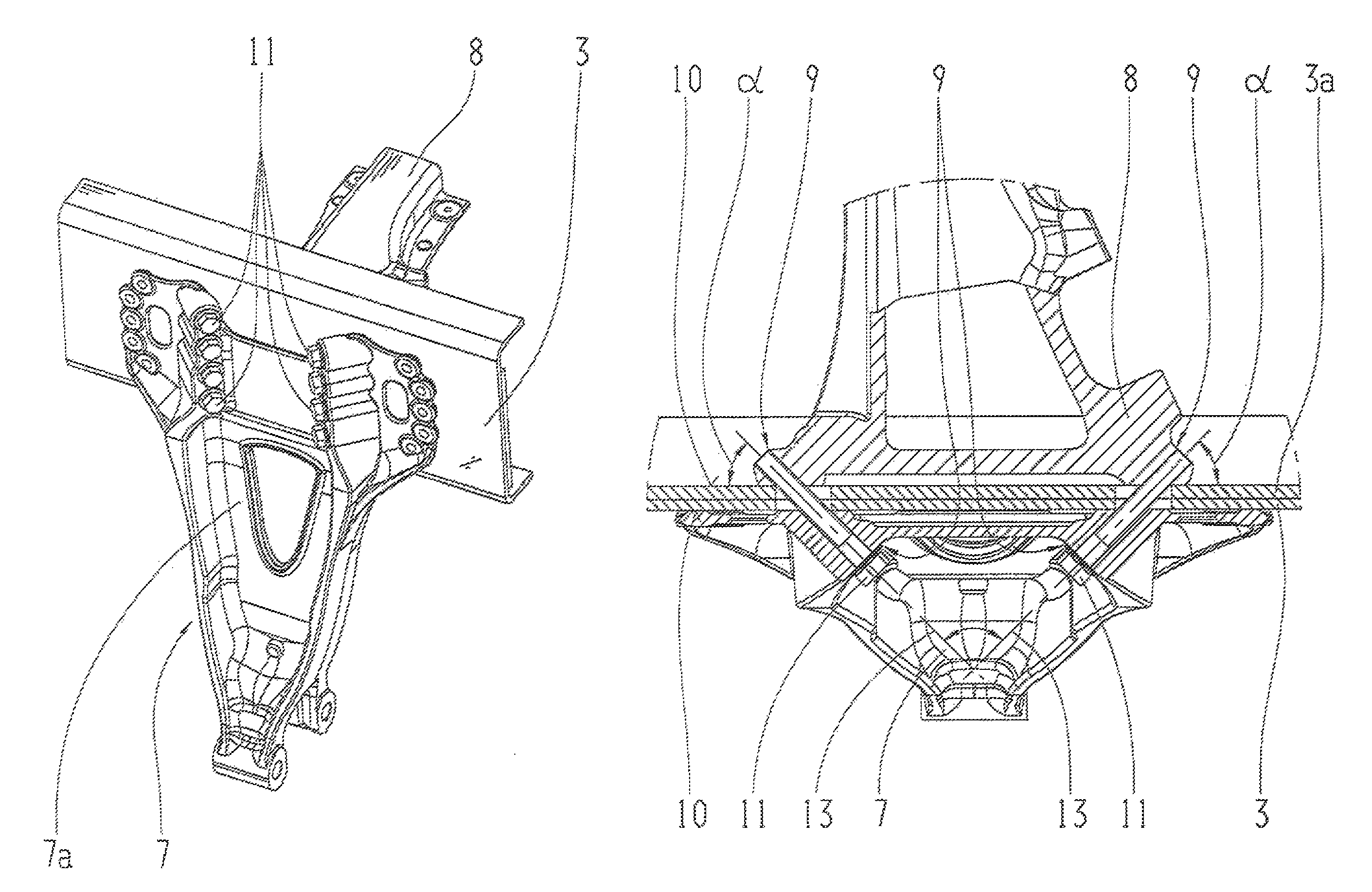
[0007]By virtue of the invention, in that at the contact surfaces the axis of each connecting means passes through the contact surface at an angle different from 90°, the result is that the force of the screw connection is divided into a normal and a transverse component. Thus, a shape-interlocking component is produced which allows the pre-stressing proportion to be increased considerably. Consequently, on the one hand, this allows the nominal screw size to be reduced, thus saving material costs and weight. Furthermore, the tightening process for the screw connection can be substantially less precise, so that process costs are reduced and the reliability of the joint is increased. Thanks to the smaller screws the fitting space required is also reduced. Optimally, such screw joints are at least essentially only loaded in tension. Moreover, the demands on surface quality can also be less strict.
[0010]If when viewed from above the contact surfaces are inclined relative to a longitudinal and a transverse axis of the vehicle, the main force directions between the axis and the vehicle frame, namely transverse and longitudinal movements, also act at an angle to the contact surfaces and therefore assist to a lesser extent the shearing of the components connected there relative to one another, so that the security of the joint is enhanced additionally. A further contribution to this security against the action of forces in the plane of the contact surfaces is provided by corrugating the contact surfaces or adopting similar, friction-promoting measures.
[0012]Particularly favorable for high stability are connecting means arranged in a common plane, especially a horizontal plane, in each case in pairs and at an angle to one another.

Problems solved by technology

This entails higher material costs and additional weight of the components.
However, for the desired lightweight designs and because of the need for more compact fitting spaces, screw joints have to be optimized in relation to weight and size.

Method used


Image

  • Motor vehicle with a vehicle frame
  • Motor vehicle with a vehicle frame
  • Motor vehicle with a vehicle frame

Examples


Embodiment Construction

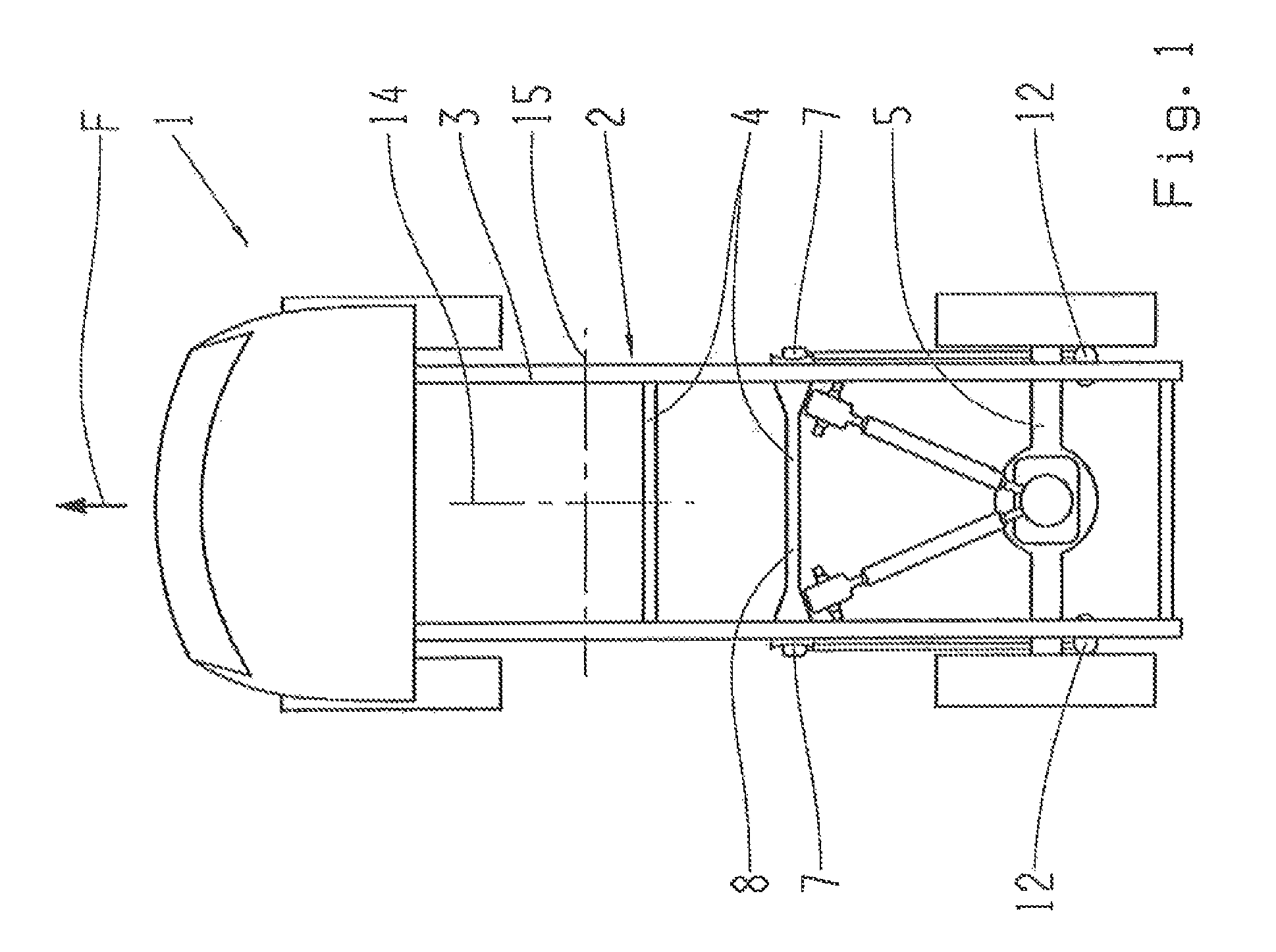
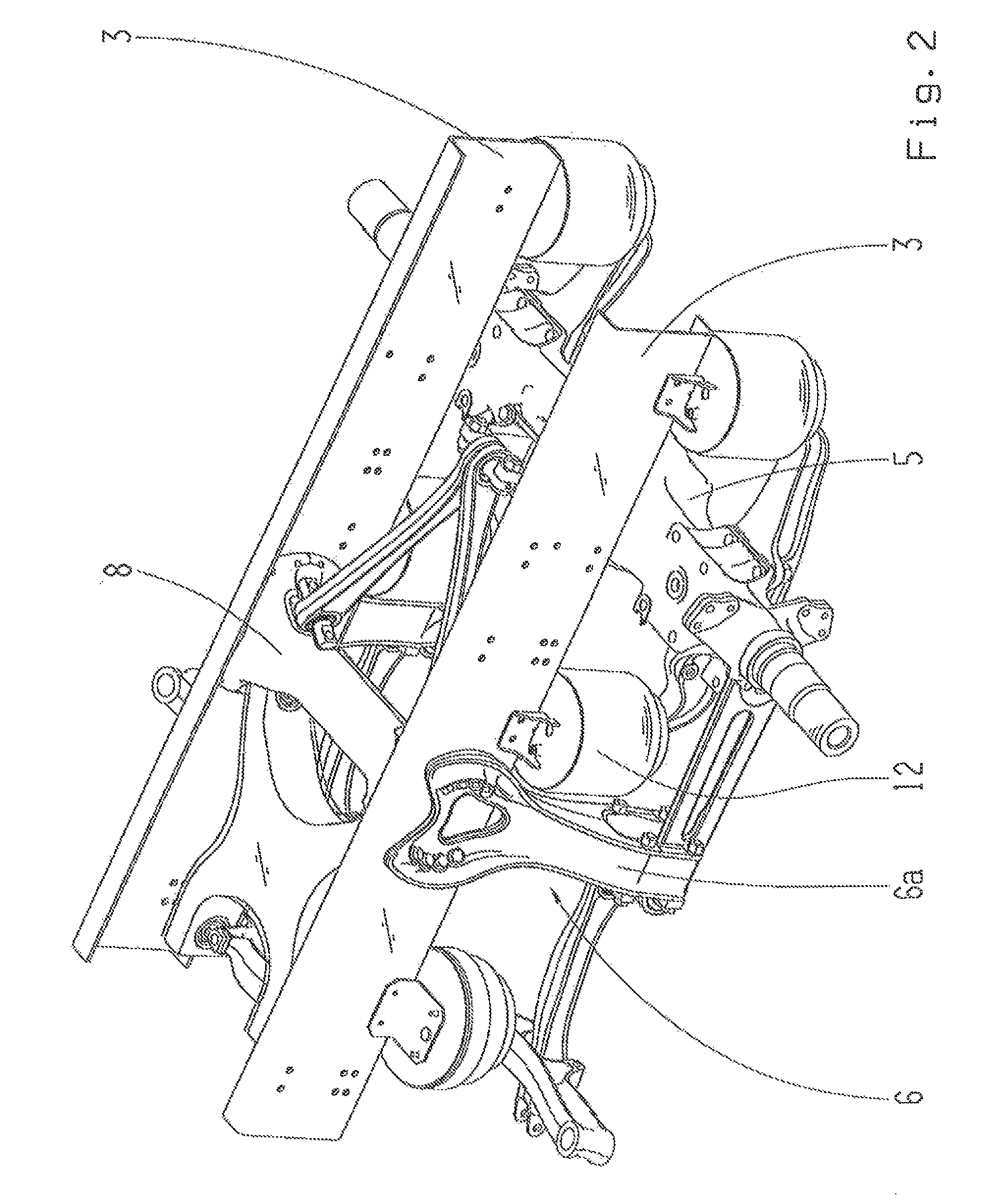
[0029]The motor vehicle 1 shown schematically in FIG. 1 is in this case a utility vehicle (UV) and comprises a vehicle frame 2 and / or a sub-frame 2a such as the air spring support shown in FIG. 8. Typically, a vehicle frame 2 can comprise two longitudinal support members 3 and a plurality of transverse support members 4, and can be variously designed as a whole. At least one axle 5, for example a rear axle, is coupled to the vehicle frame 2.

[0030]Again as examples, a building-site vehicle or an off-road vehicle can be designed in accordance with the invention.

[0031]Contact surfaces 10, 10a in particular are positioned transversely to and / or along the driving direction F, the surfaces serving as connecting surfaces on which further structural units can be fixed. For example, longitudinally extending contact surfaces 10 can be formed by the outsides or insides of the longitudinal support members 3, and transverse contact surfaces 10a for example by an extended differential of the axle...


PUM


Abstract

A motor vehicle, in particular a utility vehicle (UV), with a vehicle frame and / or a sub-frame (2; 2a) that has contact surfaces (10; 10a) extending transversely and / or longitudinally relative to the driving direction (F) and are connection surfaces to other structural units (6; 7; 8; 12). The structural units are connected by connecting elements (11) that pass through the contact surfaces (10; 10a). The connecting elements each define an axis (13) and are aligned such that the axes of the connecting elements extend through the contact surface (10; 10a) at an angle different from 90°.

Description

[0001]This application is a National Stage completion of PCT / EP2013 / 061651 filed Jun. 6, 2013, which claims priority from German patent application serial no. 10 2012 013 148.8 filed Jul. 3, 2012.FIELD OF THE INVENTION[0002]The invention concerns a motor vehicle, in particular a utility vehicle (UV), having a vehicle frame which comprises contact surfaces, in particular positioned transversely to and / or along the driving direction and forming connection surfaces to further structural units connected by connecting means that pass through the contact surfaces.BACKGROUND OF THE INVENTION[0003]Most screw-bolts that secure structural units to vehicle frames in the chassis area are loaded by thrust (shear) parallel to the contact surface between the frame portion and the structural unit connected thereto, and therefore transversely to the axis of the bolt. Typically during braking or acceleration large forces are produced in the longitudinal direction of the vehicle, which in the case of ...

Claims


Application Information

Patent Timeline
Patent Type & Authority Patents(United States)
IPC IPC(8): B62D21/02B60G11/28B60G11/27B62D21/11B62D27/06B60G7/02B60G9/00
CPCB62D21/02B60G7/02B60G9/003B60G11/27B60G11/28B62D21/11B62D27/065B60G2200/31B60G2200/343B60G2202/152B60G2202/1524B60G2204/126B60G2204/143B60G2204/15B60G2204/4302B60G2204/61B60G2206/601B60G2300/02B60G2300/40B62D21/00B62D27/06B62D33/00
Inventor SCHEPER, FRANKEISMANN, JENSLANGHORST, FRIEDHELMKNOPP, SOREN
Owner ZF FRIEDRICHSHAFEN AG
Learn More