Transmission line resonator, band-pass filter and branching filter

a technology of bandpass filter and transceiver, which is applied in the direction of resonators, electrical devices, coupling devices, etc., can solve the problems of high line impedance, limit in downsizing, and the resonator's size increases, so as to reduce the loss and higher q values, and reduce the size of the resonator

Active Publication Date: 2016-05-31
UNIVERSITY OF ELECTRO-COMMUNICATIONS
View PDF9 Cites 0 Cited by
  • Summary
  • Abstract
  • Description
  • Claims
  • Application Information

AI Technical Summary

Benefits of technology

[0013]One or more embodiments of the present invention accordingly aims to provide a resonator to achieve both of further downsizing and reductions in loss or higher Q values in a resonator of half-wave type. It further aims to provide high frequency circuits using such resonators.
[0018]According to the transmission line resonator with distributed coupled lines of one or more embodiments of the present invention, since distributed coupled lines are respectively connected to both ends of a single transmission line resonator of half-wave type and are short-circuit grounded by means of the distributed coupled lines, the line impedance of the short-circuit grounding portion can be lowered so that it is possible to achieve reductions in loss and higher Q values. In one or more embodiments, since the resonance frequency is reduced by increasing the coupling coefficient which is given by the even mode impedance and the odd mode impedance for the distributed coupled lines, it is possible to reduce the size of the resonator provided that the resonance frequency is constant.
[0019]By using the transmission line resonator with distributed coupled lines according to one or more embodiments of the present invention, it is possible to realize a large variety of high frequency circuits of small size and low loss such as a multi-staged band-pass filter, a polarized filter, an electronic tuning type filter or a multiplexer.

Problems solved by technology

While a both-end short-circuited type SIR might be an option, it will result in a drawback that the resonator increases in size.
However, there are limits in downsizing even if uniform lines are changed to SIRs or loaded with capacitances for the aim of downsizing.
Further, in case of both-end short-circuited type SIRs, it is necessary to narrow the line width of transmission lines with short-circuit grounding portions for achieving downsizing which will result in high line impedance in that it becomes difficult to achieve reductions in loss or higher Q values.

Method used


Image

  • Transmission line resonator, band-pass filter and branching filter
  • Transmission line resonator, band-pass filter and branching filter
  • Transmission line resonator, band-pass filter and branching filter

Examples


Embodiment Construction

[0035]In embodiments of the invention, numerous specific details are set forth in order to provide a more thorough understanding of the invention. However, it will be apparent to one with ordinary skill in the art that the invention may be practiced without these specific details. In other instances, well-known features have not been described in detail to avoid obscuring the invention.

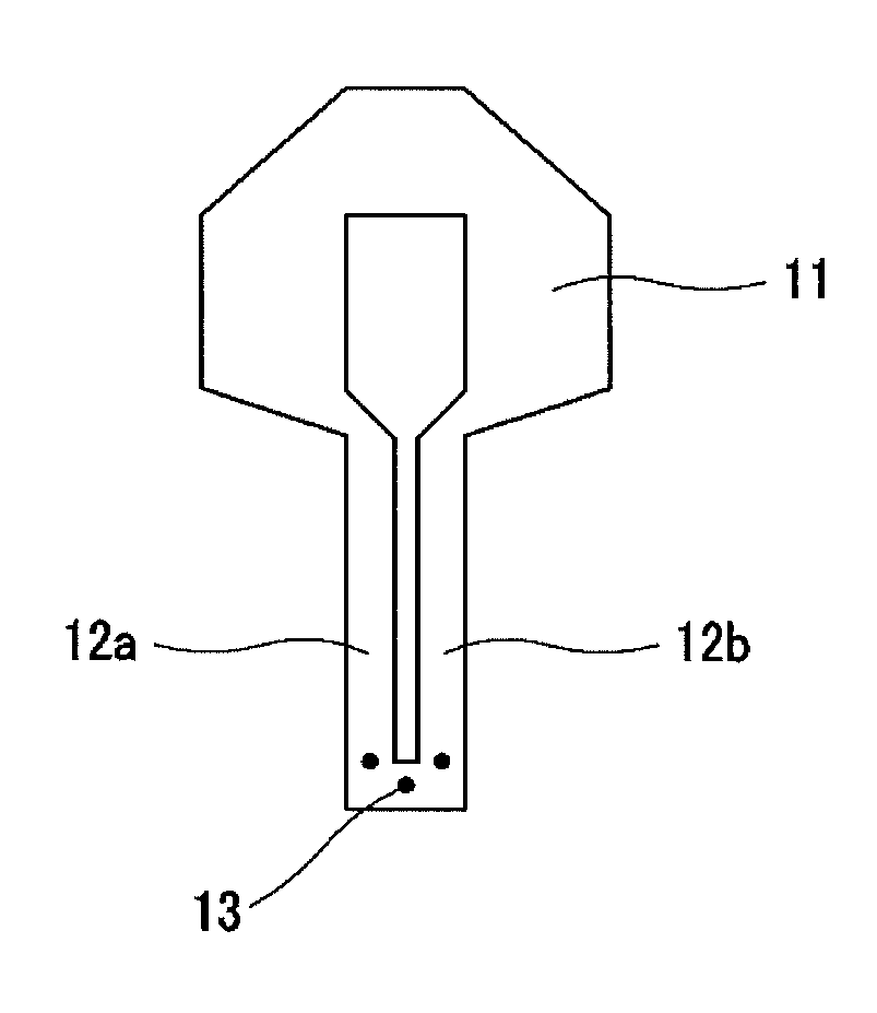
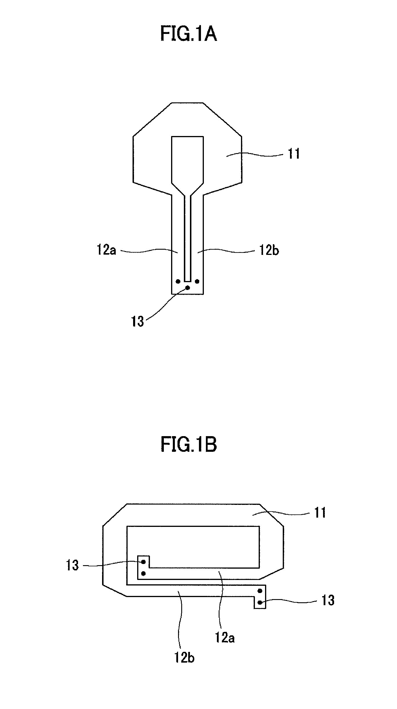
[0036]The transmission line resonator with distributed coupled lines to which one or more embodiments of the present invention is applied (hereinafter simply referred to as “transmission line resonator” or “resonator”), the band-pass filter, the cross-coupled filter, the electronic tuning type filter and the multiplexer using the transmission line resonator will now be explained in the following order with reference to the drawings.

[0037]1. Transmission line resonator

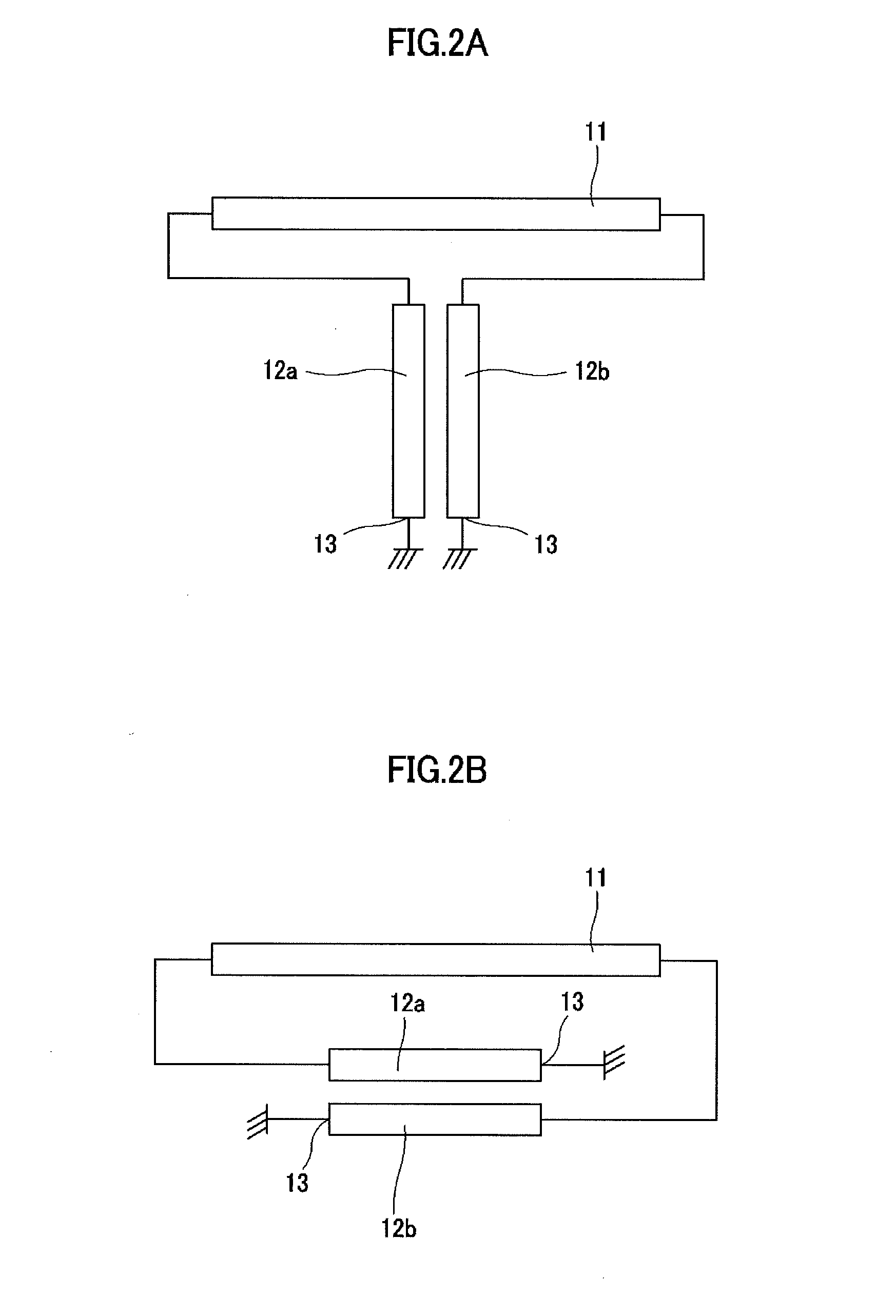
[0038]1-1. Configuration of the transmission line resonator

[0039]1-2. Operating principles of the transmission line resonator

[0040]1-3. ...


PUM


Abstract

A transmission line resonator includes distributed coupled lines including first distributed constant line which one ends are connected to a short-circuit grounding portion and second distributed constant line which is disposed in parallel to the first distributed constant line while being separated therefrom by a predetermined distance and which one ends opposing the short-circuit grounded one ends of the first distributed constant line are connected to the short-circuit grounding portion, and a single transmission line which both ends are connected to the respective other ends of the distributed coupled lines.

Description

CROSS-REFERENCE TO RELATED APPLICATIONS[0001]The present application is a U.S. national phase application of International Application No. PCT / JP2012 / 075536 filed on Oct. 2, 2012, which claims priority to JP Patent Application 2011-222918 filed in Japan on Oct. 7, 2011, the full contents of which are incorporated by reference into the present application.FIELD OF THE INVENTION[0002]The present invention relates to a transmission line resonator that is used in high frequency circuits, and particularly to a transmission line resonator using distributed coupled lines, a band-pass filter and a multiplexer which use these transmission line resonators.BACKGROUND OF THE INVENTION[0003]Main types of resonators that are used in high frequency bands and microwave bands are uniform line resonators of quarter-wave type or half-wave type. In these days, stepped impedance resonators (hereinafter also referred to as SIRs) comprised of a plurality of transmission lines of different line impedances ...

Claims


Application Information

Patent Timeline
Patent Type & Authority Patents(United States)
IPC IPC(8): H01P5/12H01P1/20H01P5/18H01P7/08H01P1/203
CPCH01P7/08H01P1/20H01P1/20381H01P5/184H01P7/082
Inventor WADA, KOJISAGAWA, MORIKAZUMAKIMOTO, MITSUO
Owner UNIVERSITY OF ELECTRO-COMMUNICATIONS
Why Eureka
Try Eureka