Method for self-adaptively demodulating quasi-orthogonal signals, demodulation unit and radio signal receiver

a quasi-orthogonal signal and demodulation unit technology, applied in the field of radio communication, can solve problems such as rare situations, problems that cannot be observed, and the operation of the receiver is not optimal most, and achieve the effect of reducing calculations and thus consumption

Active Publication Date: 2016-05-31
COMMISSARIAT A LENERGIE ATOMIQUE ET AUX ENERGIES ALTERNATIVES
View PDF4 Cites 0 Cited by
  • Summary
  • Abstract
  • Description
  • Claims
  • Application Information

AI Technical Summary

Benefits of technology

[0013]The invention aims at providing a technique enabling the performance / consumption operating point of the demodulation to be adapted to minimize calculations and thus consumption while ensuring the same performances overall in terms of error rate as the previously mentioned optimum solution.
[0018]Using the deviation between the two largest correlation values to decide whether to change the number of masked modulation bits allows to be sensitive to different parameters that can influence the difference between the two maxima. This sensitivity ensures good performance in terms of error rates, while minimizing consumption.

Problems solved by technology

But, this situation is only rarely reached since it represents an extreme case.
Consequently, the operation of the receiver is not optimum most of the time since there is extra calculation and consumption regarding the performances imposed by the standard.
Concretely, in the case of the demodulation of IEEE 802.15.4 signals, this problem can be observed on the correlation levels achieved.
If a risk factor such as a very loud noise in comparison with the orthogonality between the sequences appears, a detection error can occur.
However, if this operating margin ensures an errorless demodulation, it is over-evaluated most of the time because of the variability of the signal quality which is not always very poor.

Method used


Image

  • Method for self-adaptively demodulating quasi-orthogonal signals, demodulation unit and radio signal receiver
  • Method for self-adaptively demodulating quasi-orthogonal signals, demodulation unit and radio signal receiver
  • Method for self-adaptively demodulating quasi-orthogonal signals, demodulation unit and radio signal receiver

Examples


Embodiment Construction

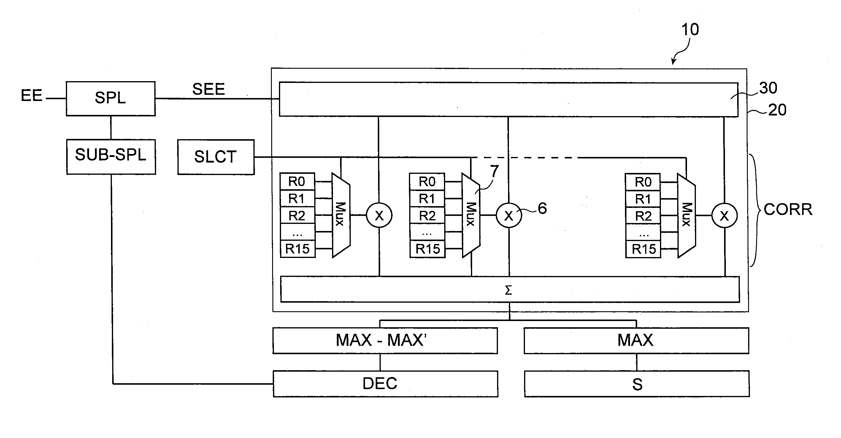
[0032]The invention relates to a method for decoding a data symbol carried by a signal received by a receiver of a communication system. The invention also extends to a demodulation unit of a receiver for a communication system configured to enable this decoding method to be implemented.

[0033]Within the scope of the invention, the data symbol received by the receiver is modulated by a spread code sequence selected from a plurality of spread code sequences being quasi-orthogonal to each other to differentiate the symbol from other data symbols. It is received in the form of a set of modulation bits.

[0034]The invention is applicable in particular, but non-exclusively, to a direct sequence spread spectrum (DSSS), meeting IEE 802.15.4™-2011 standard. In particular, the invention is not limited to the O-QPSK modulation recommended by this standard, its principle remaining valid whatever the transmission type provided that an orthogonality between the spreading sequences enables them to b...


PUM


Abstract

A method for decoding a data symbol carried by a signal received by a receiver of a communication system, the data symbol being modulated by a spread code sequence selected from a plurality of spread code sequences being quasi-orthogonal to each other to differentiate the symbol from other data symbols, and being received as a set of modulation bits, the method including a step of correlating the modulated data symbol received with each of the plurality of spread code sequences, and the correlating step is preceded by a step of sub-sampling the modulated data symbol received to mask one or more of the modulation bits therein, such that the step of correlating the sub-sampled data symbol received is carried out only for the non-masked modulation bits. It extends to a demodulation unit configured for the implementation of this method, and to a receiver integrating such a unit.

Description

TECHNICAL FIELD[0001]The field of the invention is that of radio communications, and more particularly that of the demodulation of radio signals modulated according to the direct sequence spread spectrum technique.STATE OF PRIOR ART[0002]IEEE 802.15.4 standard, which defines in particular the physical layer of the low consumption protocol ZigBee intended to be used in the ISM (“Industrial, Scientific, and Medical”) band at 2 450 MHz, is based on the direct sequence spread spectrum to transmit data, which is coupled with an O-QPSK (“Offset Quadrature Phase Shift Keying”) type phase digital modulation.[0003]The information to be transmitted is initially in the form of a stream of binary data (bits). These bits are grouped together by 4 which induces 16 possible combinations, that is 16 data symbols. Each of these symbols is then spread onto 32 “chips” (modulation bits) by a spectrum spreading sequence of its own and enables the symbol thus modulated to be differentiated from the other...

Claims


Application Information

Patent Timeline
Patent Type & Authority Patents(United States)
IPC IPC(8): H04B1/00H04B1/709H04B1/7075H04L27/22H04L27/26
CPCH04B1/709H04B1/70752H04L27/22H04L27/2601H04B2201/70713
Inventor LENOIR, VINCENTLATTARD, DIDIERLOMBARDI, WARODY
Owner COMMISSARIAT A LENERGIE ATOMIQUE ET AUX ENERGIES ALTERNATIVES
Why Eureka
Try Eureka