
Error correction processing circuit in memory and error correction processing method

a technology of error correction and processing circuit, which is applied in the field of circuits and methods for processing errors, can solve the problems of increasing the probability of occurrence of errors, deteriorating whole output quality, and error may occur in the memory including the write circuit, so as to reduce the whole power consumption and reduce the error rate. the effect of power consumption and calculation result errors

Active Publication Date: 2018-05-29
KOREA UNIV RES & BUSINESS FOUND
View PDF18 Cites 3 Cited by
  • Summary
  • Abstract
  • Description
  • Claims
  • Application Information

AI Technical Summary

Benefits of technology

[0010]In addition, some example embodiments provide an error correction processing circuit and an error correction processing method, which are capable of reducing whole power consumption by turning off some components of a decoder implementing decoding.
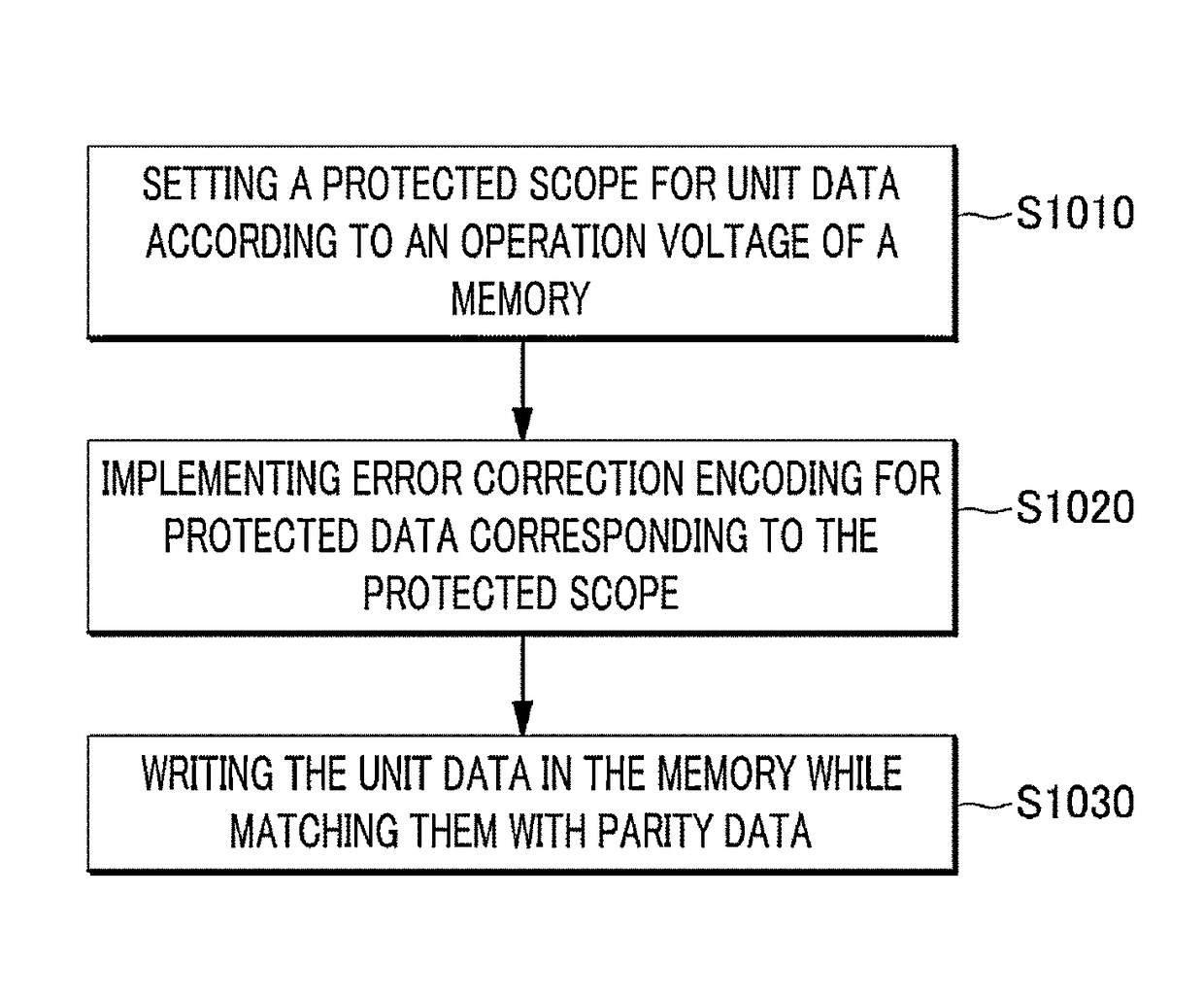
[0014]The error correction processing circuit and the error correction processing method according to an example embodiment are advantageous in that they can minimize power consumption and calculation result errors, by implementing error correction encoding for protected data corresponding to a protected scope among unit data.
[0015]Further, the error correction processing circuit and the error correction processing method according to an example embodiment can clearly correct an error occurring in protected data, by implementing error correction decoding for protected data, for which error correction encoding has been implemented, based on read-out parity data and information about a protected scope. In addition, an example embodiment can reduce whole power consumption by turning off unnecessary components, in implementing error correction decoding.

Problems solved by technology

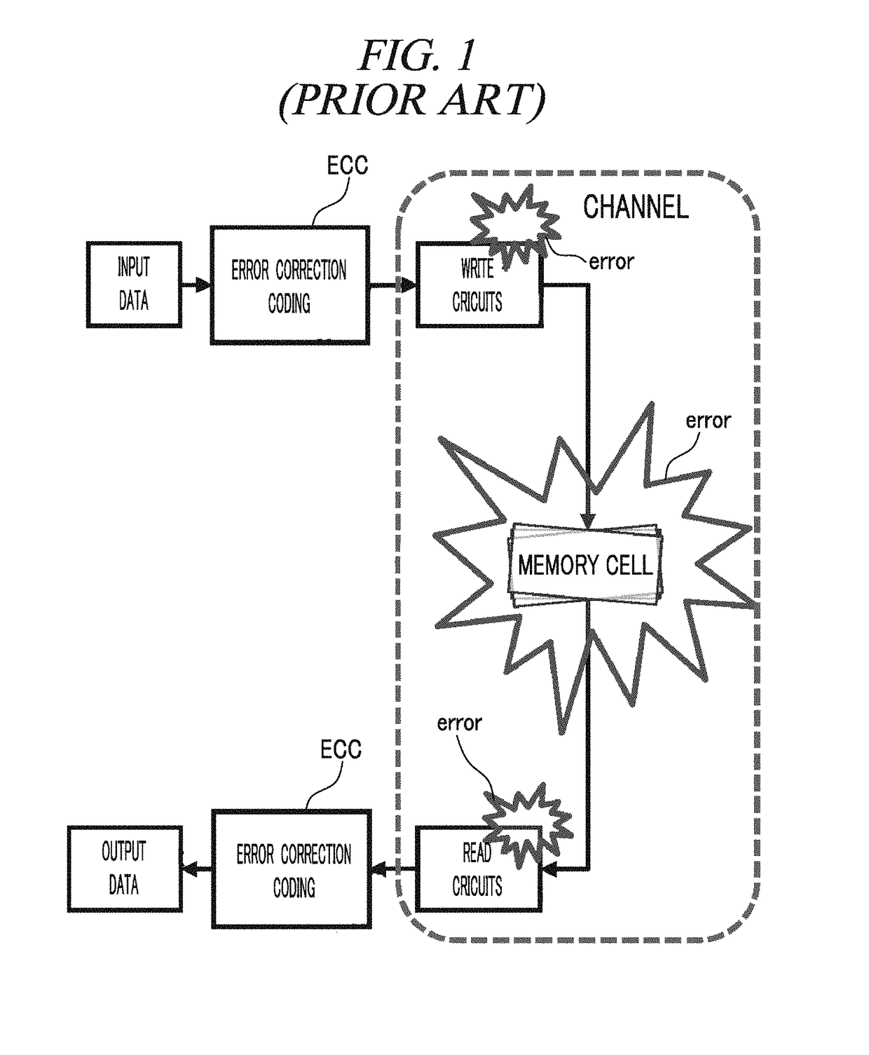
In this case, an error may occur in the memory including the write circuit, the readout circuit and the memory cell.
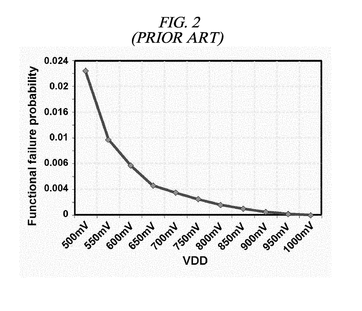
However, there is a problem in that probability of occurrence of an error increases as in FIG. 2 as the operation voltage of the memory is lowered. FIG. 2 is a graph showing error probability varying depending on an operation voltage of a memory.
That is, when an operation voltage of hardware is reduced, power consumption can be reduced, but probability of occurrence of an error at the vicinity of the memory increases, and thereby, deteriorating whole output quality.

Method used


Image

  • Error correction processing circuit in memory and error correction processing method
  • Error correction processing circuit in memory and error correction processing method
  • Error correction processing circuit in memory and error correction processing method

Examples


Embodiment Construction

[0031]Hereinafter, example embodiments will be described in detail with reference to the accompanying drawings so that inventive concept may be readily implemented by those skilled in the art. However, it is to be noted that the present disclosure is not limited to the example embodiments but can be realized in various other ways. In the drawings, certain parts not directly relevant to the description are omitted to enhance the clarity of the drawings, and like reference numerals denote like parts throughout the whole document.

[0032]Throughout the whole document, the term “comprises or includes” and / or “comprising or including” used in the document means that one or more other components, steps, operations, and / or the existence or addition of elements are not excluded in addition to the described components, steps, operations and / or elements.

[0033]FIG. 3 is a block diagram illustrating a whole structure of an error correction processing circuit according to an example embodiment.

[00...


PUM


Abstract

A method for correcting error in a memory comprises setting a protected scope for at least part of unit data to be written in the memory according to an operation voltage of the memory; implementing error correction encoding for protected data corresponding to the protected scope among the unit data; and writing the unit data in the memory while matching them with parity data generated as a result of the error correction encoding.

Description

CROSS-REFERENCE TO RELATED APPLICATION[0001]This Application is a continuation application of PCT Application No. PCT / KR2014 / 001926 filed on Mar. 10, 2014, which claims the benefit of Korean Patent Application No. 10-2013-0025034 filed on Mar. 8, 2013, the entire disclosures of which are incorporated herein by reference.TECHNICAL FIELD[0002]The embodiments described herein pertain generally to a circuit and a method for processing an error, in particular, a circuit and a method for correcting and processing an error occurring in a memory.BACKGROUND ART[0003]An error correction code (ECC) refers to an encoding (channel encoding) method for incorporating enough redundant information into a data block to be transmitted such that a receiver can deduce what characters to be transmitted are. The error correction code is essential in digital communication, and has been applied even to the inside of hardware for data storage and transmission.[0004]FIG. 1 is a diagram for describing a concep...

Claims


Application Information

Patent Timeline
Patent Type & Authority Patents(United States)
IPC IPC(8): H03M13/35H03M13/00H03M13/15G06F11/10H03M13/05
CPCH03M13/35G06F11/1004G06F11/1048H03M13/611H03M13/152H03M13/155H03M13/1545H03M13/05G06F11/10
Inventor PARK, JONG SUNPARK, JANG WON
Owner KOREA UNIV RES & BUSINESS FOUND
Learn More