Protective structure for tank top fittings

a protective structure and tank technology, applied in the field of railway tank cars, can solve the problems of nozzles susceptible to being broken loose from the tank, valve breakage, failure of protective structures, etc., and achieve the effect of avoiding weight and efficiently adding weigh

Active Publication Date: 2016-06-07
GUNDERSON
View PDF33 Cites 4 Cited by
  • Summary
  • Abstract
  • Description
  • Claims
  • Application Information

AI Technical Summary

Benefits of technology

[0002]Nozzles have long been provided on the top of a railway tank car as manways and as locations for mounting groups of valves, including those used to fill a cargo tank with a fluid cargo, to remove the fluid cargo from the cargo tank, and to protect against excessive internal pressure. It has long been recognized that the nozzles are susceptible to being broken loose from the tank and that the valves can be broken in the event of a rollover of a railway tank car. Various housings have been used in the past to protect the valves, but they have been attached to a nozzle or a valve-mounting plate fastened to a nozzle. Various strengthened and reinforced nozzle structures have been provided in order to resist breakage of the nozzles in the case of a rollover, but previously known protective structures have failed when tank cars have overturned while moving along a railway.
[0004]At least until recently, it had been considered unnecessary and an undesirable addition of weight to a railroad tank car to provide a strong protective structure surrounding a manway nozzle or a valve group nozzle on the top of a railroad tank car. Instead, welded gussets and various arrangements of strengthening of the attachment of a nozzle to the top of a cargo tank had been used in the past, as well as protective bells that can be attached to the valve group mounting plate to surround the valves and protect the valves themselves from damage in collisions and overturning. While previously available protection for the top of a tank car has value, various events have recently proven that protection to be insufficient in the case of overturning of railroad tank cars in motion along a railroad track.
[0005]What is needed, then, is a substantial yet not overly massive structure for protecting the various valves on the top of a cargo tank of a railway tank car, to prevent loss of cargo, and particularly to prevent escape of dangerous gaseous cargo or flammable liquid cargo, in the event of derailment and overturning of a moving railway tank car. Such a protective structure should not be so heavy as to add significantly to the fuel requirements for moving the car along the railway, yet it should be of ample strength. It is desirable also to have a protective structure on the top of a cargo tank be no larger than necessary, in order that it be a smaller target which can collide with an obstruction on the ground in the case of a rollover.
[0011]Such a protective structure in one embodiment of the railway tank car disclosed herein includes a reinforcing band located on an upper portion of the upstanding wall to strengthen the reinforcing structure in the areas most likely to be subjected to external forces in the event of a rollover, yet avoid adding weight unnecessarily to the tank car.
[0012]The protective structure disclosed herein may be efficiently added to a conventional railway tank car to make such a car significantly less vulnerable to catastrophic damage and loss of fluid cargo in the event of a rollover.

Problems solved by technology

It has long been recognized that the nozzles are susceptible to being broken loose from the tank and that the valves can be broken in the event of a rollover of a railway tank car.
Various strengthened and reinforced nozzle structures have been provided in order to resist breakage of the nozzles in the case of a rollover, but previously known protective structures have failed when tank cars have overturned while moving along a railway.
At least until recently, it had been considered unnecessary and an undesirable addition of weight to a railroad tank car to provide a strong protective structure surrounding a manway nozzle or a valve group nozzle on the top of a railroad tank car.
While previously available protection for the top of a tank car has value, various events have recently proven that protection to be insufficient in the case of overturning of railroad tank cars in motion along a railroad track.

Method used


Image

  • Protective structure for tank top fittings
  • Protective structure for tank top fittings
  • Protective structure for tank top fittings

Examples


Embodiment Construction

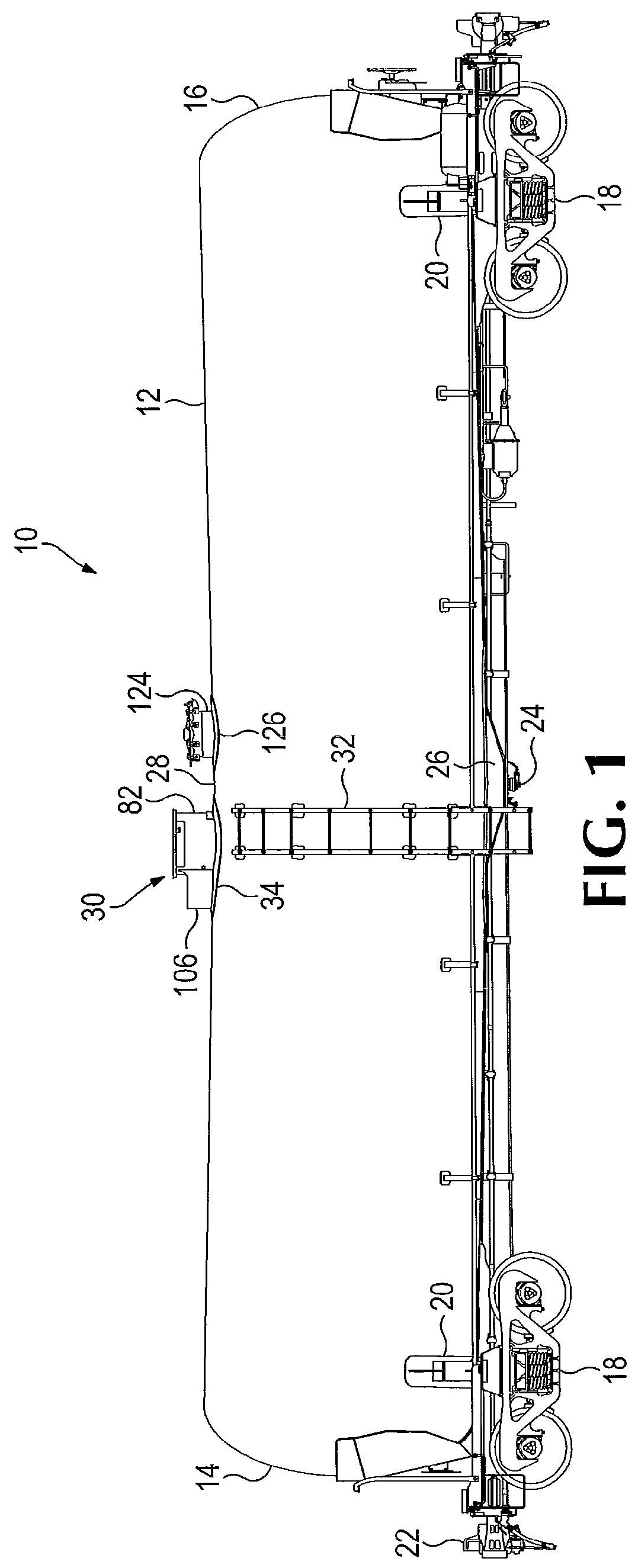
[0029]Referring now to the drawings which form a part of the disclosure herein, a railroad tank car 10 shown in FIG. 1 may include a generally cylindrical cargo tank 12 having a longitudinal axis 13. The opposite ends 14, 16 of the cargo tank 12 are closed, and the cargo tank 12 may be supported by a pair of wheeled trucks 18 that may be attached to the cargo tank 12 by appropriate conventional saddles and bolsters 20 connected with an outer surface of the cargo tank 12. The cargo tank 12 itself may be constructed with significant enough rigidity and strength not only to be self-supporting, but to bear the longitudinal train loads exerted on the tank car 10 during travel.

[0030]A conventional double shelf coupler 22 may be provided at each end of the car. Centrally located in the bottom of the cargo tank there may be a bottom outlet valve 24 and conventional protective structures 26.

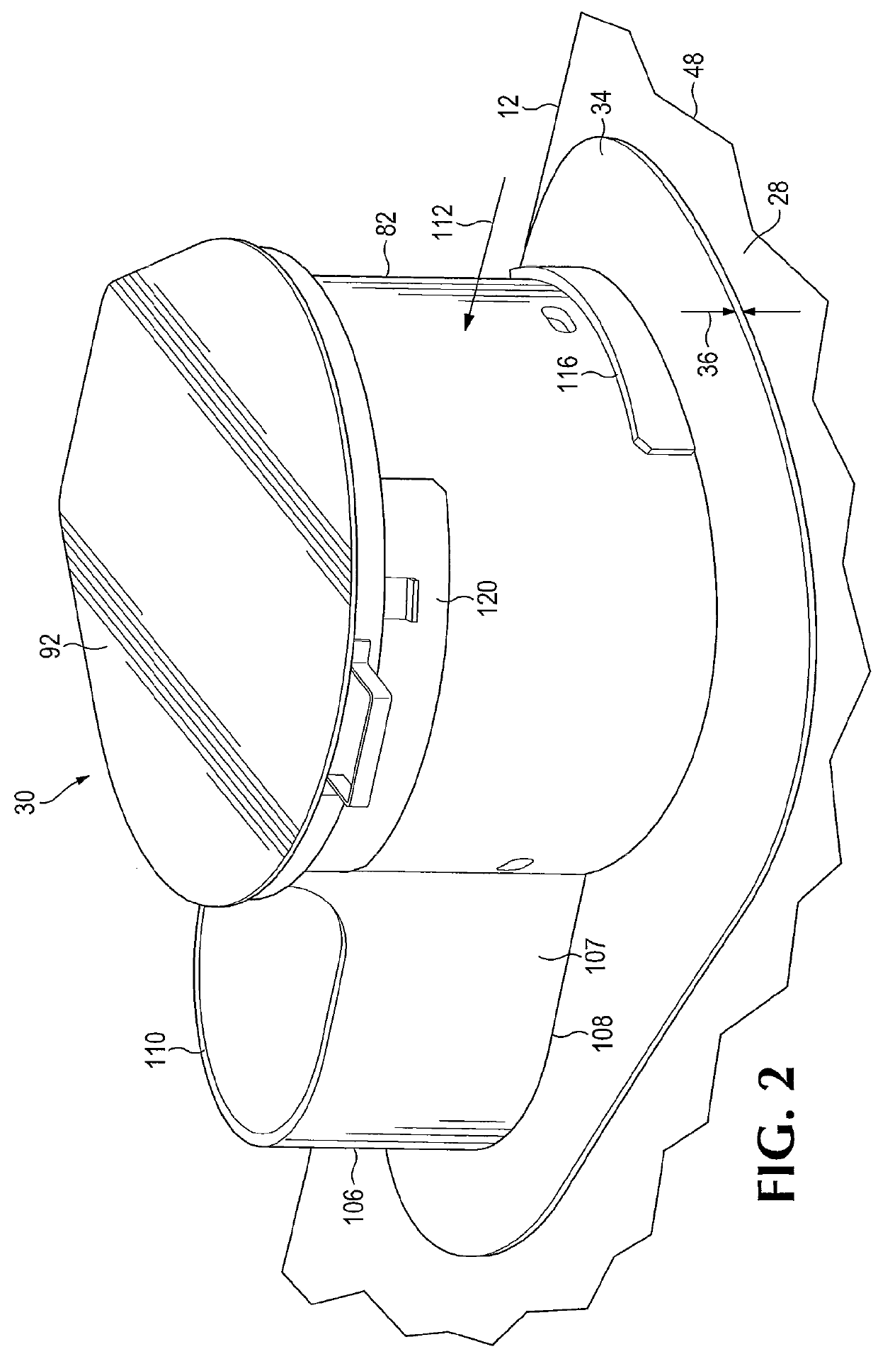
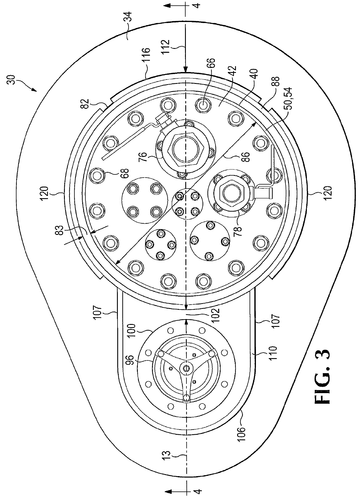
[0031]Located about mid-length of the tank car 10 and centrally along the top 28 of the cargo tank 12 ...


PUM

PropertyMeasurementUnit
radial clearance distanceaaaaaaaaaa
thicknessaaaaaaaaaa
exposure distanceaaaaaaaaaa

Abstract

A railway tank car including a protective structure for the top of its cargo tank and surrounding a valve group mounting nozzle and a pressure relief safety valve nozzle, to protect the associated valves against damage resulting from the car being overturned, particularly while the railcar is moving along a railway. The protective structure includes an upstanding wall of metal plate that surrounds and is located at a radial distance outwardly apart from the tank top valve group mounting nozzle. A reinforcing band is attached to an upper portion of the upstanding wall to enhance its strength. Also disclosed is a method of protecting fittings mounted on a nozzle on the tank top of a railway tank car by providing and mounting such a protective structure to surround the tank top nozzle and associated fittings.

Description

BACKGROUND AND SUMMARY OF THE INVENTION[0001]The present invention is related to railway tank cars and in particular to a protective structure for the various valves ordinarily present on the top of a cargo tank of such a railway tank car.[0002]Nozzles have long been provided on the top of a railway tank car as manways and as locations for mounting groups of valves, including those used to fill a cargo tank with a fluid cargo, to remove the fluid cargo from the cargo tank, and to protect against excessive internal pressure. It has long been recognized that the nozzles are susceptible to being broken loose from the tank and that the valves can be broken in the event of a rollover of a railway tank car. Various housings have been used in the past to protect the valves, but they have been attached to a nozzle or a valve-mounting plate fastened to a nozzle. Various strengthened and reinforced nozzle structures have been provided in order to resist breakage of the nozzles in the case of ...

Claims


Application Information

Patent Timeline
Patent Type & Authority Patents(United States)
IPC IPC(8): B61D5/00B65D90/00B23K31/02
CPCB61D5/08B23K31/02B23K2201/006B23K2201/12B23K2203/04B23K2101/006B23K2101/12B23K2103/04
Inventor THOMAS, BRADLEY J.
Owner GUNDERSON
Why Eureka
Try Eureka