Pressure water supply device

A technology of water supply device and pressure, which is applied in the configuration of water supply device and water supply pool, water saving, etc. It can solve the problems of pressure leakage, pressure barrel function ineffective, water cannot be completely squeezed out, etc., so as to prevent the formation of danger and improve Evacuation rate, the effect of preventing excessive internal pressure

Pending Publication Date: 2021-07-27
ZHEJIANG LONSID HEALTHY DRINKING WATER EQUIP
View PDF0 Cites 2 Cited by
  • Summary
  • Abstract
  • Description
  • Claims
  • Application Information

AI Technical Summary

Problems solved by technology

[0003] The pressure barrel must be sealed at the diaphragm / airbag and the externally inflated part. Once there is an unsealed part, resulting in pressure leakage, the entire function of the pressure barrel will not work; the diaphragm / airbag is used to squeeze the water, so the water in the barrel cannot It is completely squeezed out, and it is easy to breed bacteria inside

Method used


Image

  • Pressure water supply device
  • Pressure water supply device
  • Pressure water supply device

Examples


Embodiment Construction

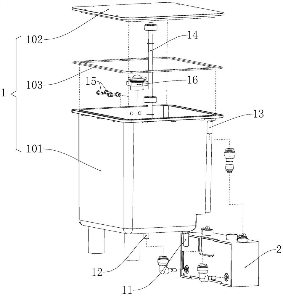
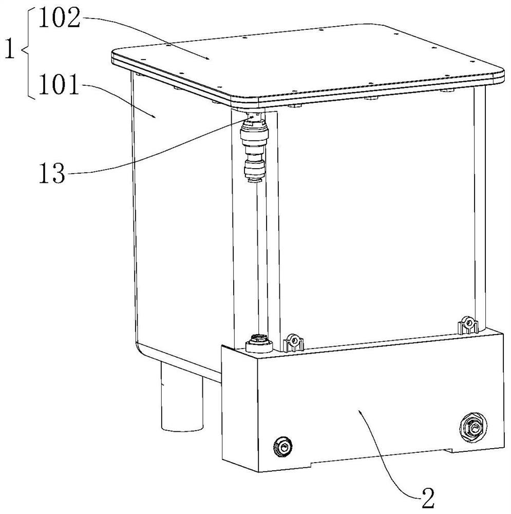
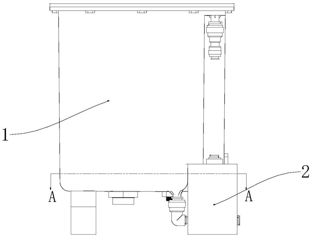
[0032] The core of the present invention is to provide a pressure water supply device, which can increase the emptying rate of the water storage tank and prevent danger caused by excessive internal pressure.

[0033] In order to enable those skilled in the art to better understand the technical solutions of the present invention, the pressure water supply device of the present invention will be described in detail below in conjunction with the accompanying drawings and specific implementation methods.

[0034] Figure 1A and Figure 1B Respectively, an explosion diagram and an assembly diagram of the pressure water supply device of the present invention; Figure 2A It is a schematic diagram of the front view direction of the pressure water supply device of the present invention, Figure 2B for Figure 2A The sectional view of the A-A direction in the middle; the pressure water supply device of the present invention includes a water storage tank 1 and a water inlet platform a...


PUM


Abstract

The invention discloses a pressure water supply device. According to the pressure water supply device, a water storage tank is a sealed tank body, a water inlet and a water outlet are formed in the lower surface of the water storage tank to achieve water inlet and water outlet correspondingly, water in an external water supply pipe flows into the water storage tank through a water inlet channel and the water inlet, and the water in the water storage tank flows to a water requiring pipe through the water outlet and a water outlet channel; the water inlet and the water outlet are formed in the lower surface of the water storage tank, so that all water can flow out of the water storage tank, and the emptying rate of the water storage tank is improved; when water needs to be drained outwards, a three-way valve enables an air pump to be in communication with the water storage tank, the water storage tank is inflated, the air pressure of the upper space of the water storage tank is increased, and water is drained outwards in an accelerated mode; when drainage is stopped, the air pump stops inflating, the three-way valve communicates the water storage tank with the outside through the air inlet and outlet end of an air supply and outlet pipe, air in the water storage tank is discharged, and the air pressure is reduced; and according to the pressure water supply device, water is drained in an inflation mode during inflation work, high air pressure cannot be continuously kept in the pressure water supply device for a long time after the pressure water supply device stops, and danger caused by too large internal pressure is prevented.

Description

technical field [0001] The invention relates to the field of water supply equipment, and further relates to a pressure water supply device. Background technique [0002] The pressure tank is a commonly used pressure water storage device nowadays. A diaphragm or air bag is installed inside the pressure tank. The diaphragm or air bag divides the inside of the pressure tank into an air storage room and a water storage room. The pressure at the water outlet is relieved by pre-filling the pressure in the air storage room. Then use the pressure difference inside and outside to squeeze out the water in the bucket. [0003] The pressure barrel must be sealed at the diaphragm / airbag and the externally inflated part. Once there is an unsealed part, resulting in pressure leakage, the entire function of the pressure barrel will not work; the diaphragm / airbag is used to squeeze the water, so the water in the barrel cannot It is completely squeezed out, and bacteria are easy to breed ins...

Claims


Application Information

Patent Timeline
IPC IPC(8): E03B11/00E03B11/08
CPCE03B11/00E03B11/08Y02A20/00
Inventor 朱锦成叶咏东张航登郑俊雪
Owner ZHEJIANG LONSID HEALTHY DRINKING WATER EQUIP
Why Eureka
Try Eureka