Ball bearing

a ball bearing and ball bearing technology, applied in the direction of rolling contact bearings, shafts and bearings, rotary bearings, etc., can solve the problems of ball bearing damage, ball bearing and track damage, and the abandonment of four-point bearings in favor of more elaborate and expensive bearing designs

Active Publication Date: 2016-06-07
IMO HOLDING GMBH
View PDF19 Cites 3 Cited by
  • Summary
  • Abstract
  • Description
  • Claims
  • Application Information

AI Technical Summary

Benefits of technology

[0012]Thus, in each case the surface of the track diverges from a predefined contact angle θP1, θP2, θP3 and θP4 in both poloidal directions compared to a circular cross section, of the kind found in a torus, for example. Although this divergence need not be very great, it nevertheless has the effect that under deformation of the rings, for example due to external radial or axial forces or tilting moments, the actual contact angles do not shift as much as they would if the tracks had a circular cross section, particularly not to extremely high values in the range of 75° or more. Thus, the edge of the track is not overloaded even when stresses are very high and the rigidity of the adjacent construction low.
[0033]Finally, it is within the teaching of the invention that the planar contact faces of both races that are to be connected each to a respective foundation, frame or other machine part or system part, are mutually offset in opposite (axial) directions on the two races, i.e., for example, the upper contact face being offset upward and the lower one downward. In this way, it is possible for both races to have approximately the same height and thus approximately the same cross section, as well as, ultimately, nearly identical stability.

Problems solved by technology

If this occurs, not only does the loading of the ball in the rest of the contact area increase, but also, in particular, heightened edge pressures are created and will soon cause damage to the balls and tracks.
Under unfavorable conditions, therefore, a four-point bearing must be abandoned in favor of a more elaborate and expensive bearing design, for example a multi-row roller bearing having at least one row of rollers with a contact angle of 90° for axial and tilting-moment loads, and at least one row of rollers with a contact angle of 0° for radial load transfer.

Method used


Image

  • Ball bearing
  • Ball bearing
  • Ball bearing

Examples


Embodiment Construction

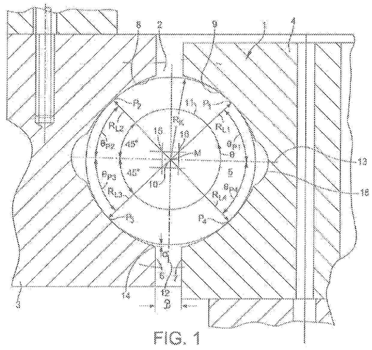
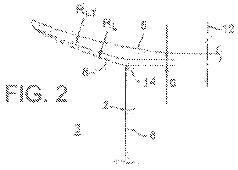
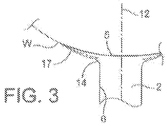
[0011]This problem is solved by the fact that the transverse radius of curvature RL of the track(s) in the vicinity of the contact angles θP1, θP2; θP3 and θP4 is always a continuous and differentiable function of the poloidal angle coordinate θ: RL=RL(θ), that increases outward from the respective contact angle region θP1, θP2; θP3 and θP4 in both poloidal directions, RL(θ)≧RL(θPv), even, where appropriate, beyond an inflection point PW, in the case of a poloidal angle θW with a transverse radius of curvature RL(θW)=±∞, and on to convex transverse radii of curvature RL(θ)<0.

[0012]Thus, in each case the surface of the track diverges from a predefined contact angle θP1, θP2, θP3 and θP4 in both poloidal directions compared to a circular cross section, of the kind found in a torus, for example. Although this divergence need not be very great, it nevertheless has the effect that under deformation of the rings, for example due to external radial or axial forces or tilting moments, the a...


PUM


Abstract

A ball bearing having first and second races and, disposed in a gap between the two races, a row of balls of radius RK that roll along facing tracks of the two races, wherein centers of the balls move on a circular path surrounded by a torus circumscribing all the balls of the row and having the toroidal radius RK, a toroidal angle coordinate φ, and a poloidal angle coordinate θ, wherein each track has with each ball two nearly punctiform contact areas P1, P2; P3 P4 at respective contact angles θP1, θP2; θP3 and θP4, wherein the cross section of the track in the region of the contact points P1 . . . P4 has a finite transverse radius of curvature RL1 . . . RL4, with RLv>RK, and wherein in the vicinity of a contact point P1 . . . P4 the transverse radius of curvature (RL) is a continuous and differentiable function of the poloidal angle coordinate θ: RL=RL(θ) that increases outward from the respective contact point P1 . . . P4 in both poloidal directions: RL(θ)≧RL(θPv).

Description

BACKGROUND OF THE INVENTION[0001]1. Field of the Invention[0002]The invention is directed to a ball bearing having a first and a second race and, disposed in a gap between the two races, at least one row of balls of radius RK, that roll along facing tracks of the two races, wherein centers of the balls of a row move on a circular path that is surrounded by a torus circumscribing all the balls of the row and having the toroidal radius RK, a toroidal angle coordinate φ and a poloidal angle coordinate θ, and wherein each track has with each ball two nearly punctiform contact areas or contact points P1, P2; P3 P4 at the respective contact angle θP1, θP2; θP3 and θN, and wherein the cross sections of the tracks in the region of the contact angles θP1, θP2; θP3 and θP4 have transverse curvatures possessing finite radii of curvature RL1 . . . RL4 each of which is greater than the ball radius RK: RLv>RK.[0003]2. Description of the Prior Art[0004]Such four-point bearings exist in various ...

Claims


Application Information

Patent Timeline
Patent Type & Authority Patents(United States)
IPC IPC(8): F16C33/58F16C19/16
CPCF16C19/166F16C33/585F16C2240/76
Inventor FRANK, HUBERTUS
Owner IMO HOLDING GMBH
Why Eureka
Try Eureka