Logical switches

a technology of logical switches and switches, applied in the field of logical switches, can solve problems such as affecting the performance of the network, the likelihood of connection, and the number of connections

Inactive Publication Date: 2016-06-07
AMAZON TECH INC
View PDF33 Cites 19 Cited by
  • Summary
  • Abstract
  • Description
  • Claims
  • Application Information

AI Technical Summary

Problems solved by technology

In addition to the significant cost of purchase and installation, the large number of connections increases the likely number of connections that are made incorrectly, and thus can affect the performance of the network.

Method used


Image

  • Logical switches
  • Logical switches
  • Logical switches

Examples


Embodiment Construction

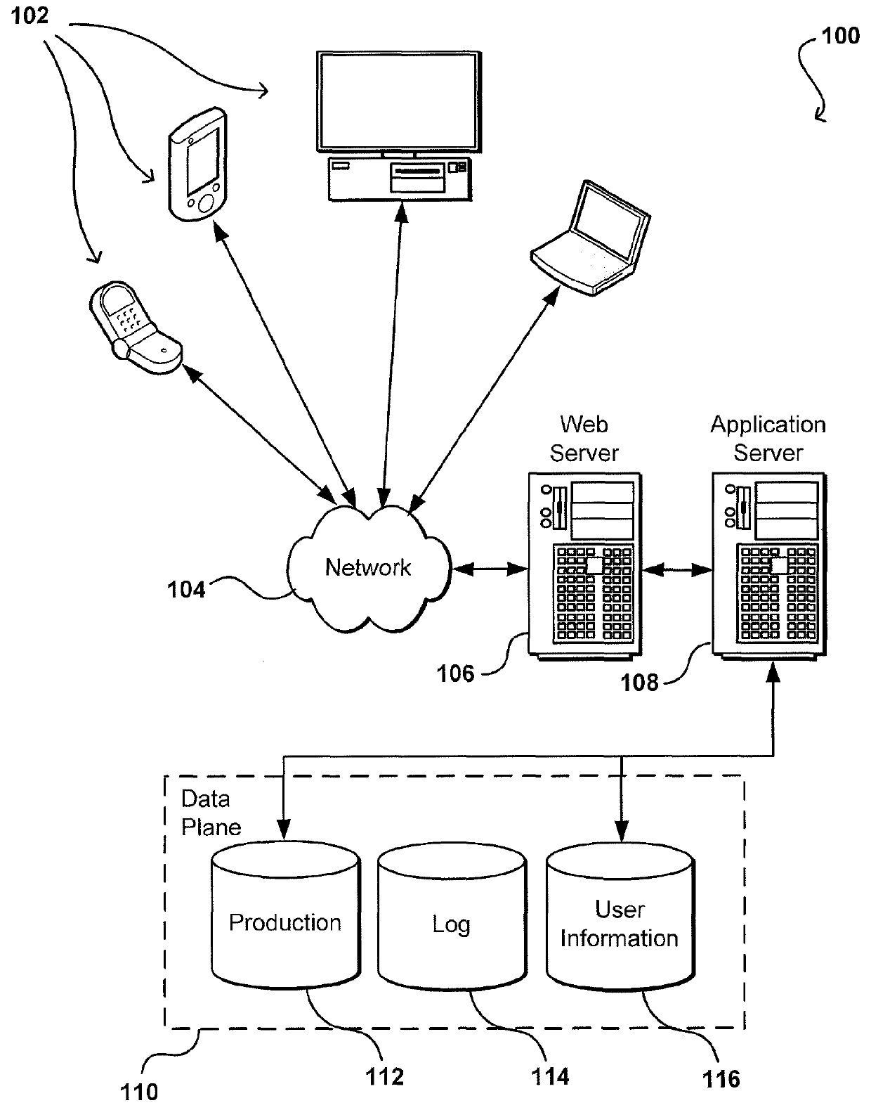
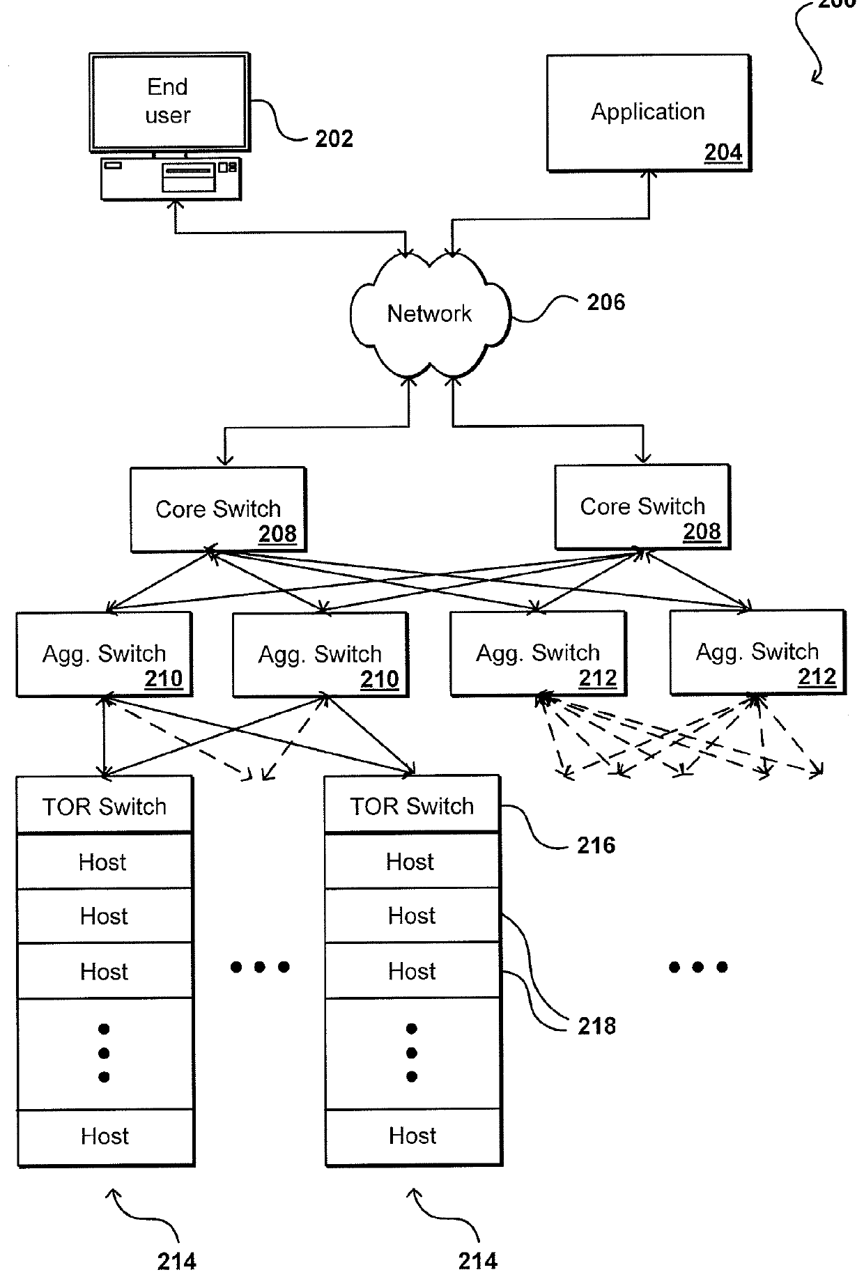
[0018]Systems and methods in accordance with various embodiments of the present disclosure may overcome one or more of the aforementioned and other deficiencies experienced in conventional approaches to deploying, connecting, maintaining, designing, and / or upgrading a network of electronic components. In computing networks such as data centers, for example, there are many levels (e.g., layers or tiers) of components and many connections between those levels. These can comprise, for example, a hierarchy of network switches connecting various host devices or other resources to an external network. The connections themselves can be made by any appropriate connection mechanism, such as fiber optic cable, network cable, copper wire, etc.

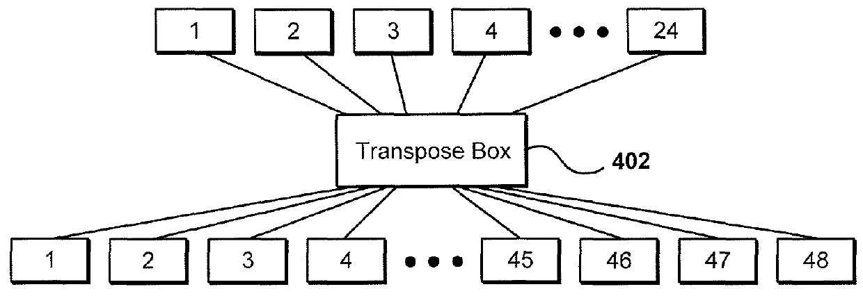
[0019]For each connection, a technician or other such person typically must connect the cable (or other connection mechanism) to one device, run the cable over a distance to another device, and connect that cable to the other appropriate device. Oftentime...


PUM


Abstract

The deployment and scaling of a network of electronic devices can be improved by utilizing one or more network transpose boxes. Each transpose box can include a number of connectors and a meshing useful for implementing a specific network topology. Different tiers of a network can be connected to one or more of the network transpose boxes, and operated as a logical switch. A control server can be used to manage the control plane operations of the logical switch.

Description

BACKGROUND[0001]As an increasing number of applications and services are being made available over networks such as the Internet, an increasing number of content, application, and / or service providers are turning to networked and shared-resource technologies, such as cloud computing. Further, there is an increasing amount of data being stored remotely, such that data centers are increasingly expanding the amount of storage capacity and related resources. A user or customer typically will rent, lease, or otherwise pay for access to resources through the cloud or across a network, and thus does not have to purchase and maintain the hardware and / or software to provide access to these resources.[0002]In many instances, a customer will require more than one resource, such as a computing device, server, or other computing or processing device, to perform portions of an operation. As the number of customers increases, and the average number of resources per customer increases, there is a c...

Claims


Application Information

Patent Timeline
Patent Type & Authority Patents(United States)
IPC IPC(8): H04L12/933H04L12/931H04L12/46H04L45/58
CPCH04L49/15H04L49/45H04L12/46H04L49/40H04L49/70H04L49/356H04L12/4625H04L45/58
Inventor JUDGE, ALAN M.KELLY, MARK N.BRAR, JAGWINDER SINGHMARR, MICHAEL DAVIDCOHN, DANIEL T.
Owner AMAZON TECH INC
Why Eureka
Try Eureka