Speckle reduction

a technology of specks and specks, applied in the field of speck reduction, can solve the problems of inability to achieve very practical techniques, inability to induce specks, and inability to add these various scattered components with relative delays

Active Publication Date: 2011-09-08
HGSKOLEN I BUSKERUD OG VESTFOLD
View PDF5 Cites 18 Cited by
  • Summary
  • Abstract
  • Description
  • Claims
  • Application Information

AI Technical Summary

Benefits of technology

According to a first aspect, there is provided a speckle reduction apparatus comprising: a radiation path and a mask arranged within the radiation path, the mask comprising an array of electrically controllable cells configured to form a pattern on the mask that varies with time. Electrical control of each cell removes the need to mechanically move the mask, which instead changes pattern, typically at the same rate or faster than an integration time of a detector. In other words, the mask may remain stationary or static with respect to the radiation path in use. The radiation may be light of any wavelength including, for example, radio waves, microwaves and ultraviolet waves. In particular, speckle may be a present from lasers or other coherent sources. The radiation may also be sound waves and for example, ultrasonic radiation used in ultrasound imaging.

Problems solved by technology

Speckle is induced by light interference emerging from a screen.
Propagation of this reflected light to a distant observation point results in the addition of these various scattered components with relative delays, which may vary from several to many wavelengths.
However, this technique may not be very practical due to the required high-power actuator.
However, the special designed laser arrays may increase costs accordingly.
However, the mechanical components required in this approach limit the technique and are impractical, especially when a high order HM is introduced to achieve a higher degree of speckle reduction.

Method used


Image

  • Speckle reduction
  • Speckle reduction
  • Speckle reduction

Examples


Embodiment Construction

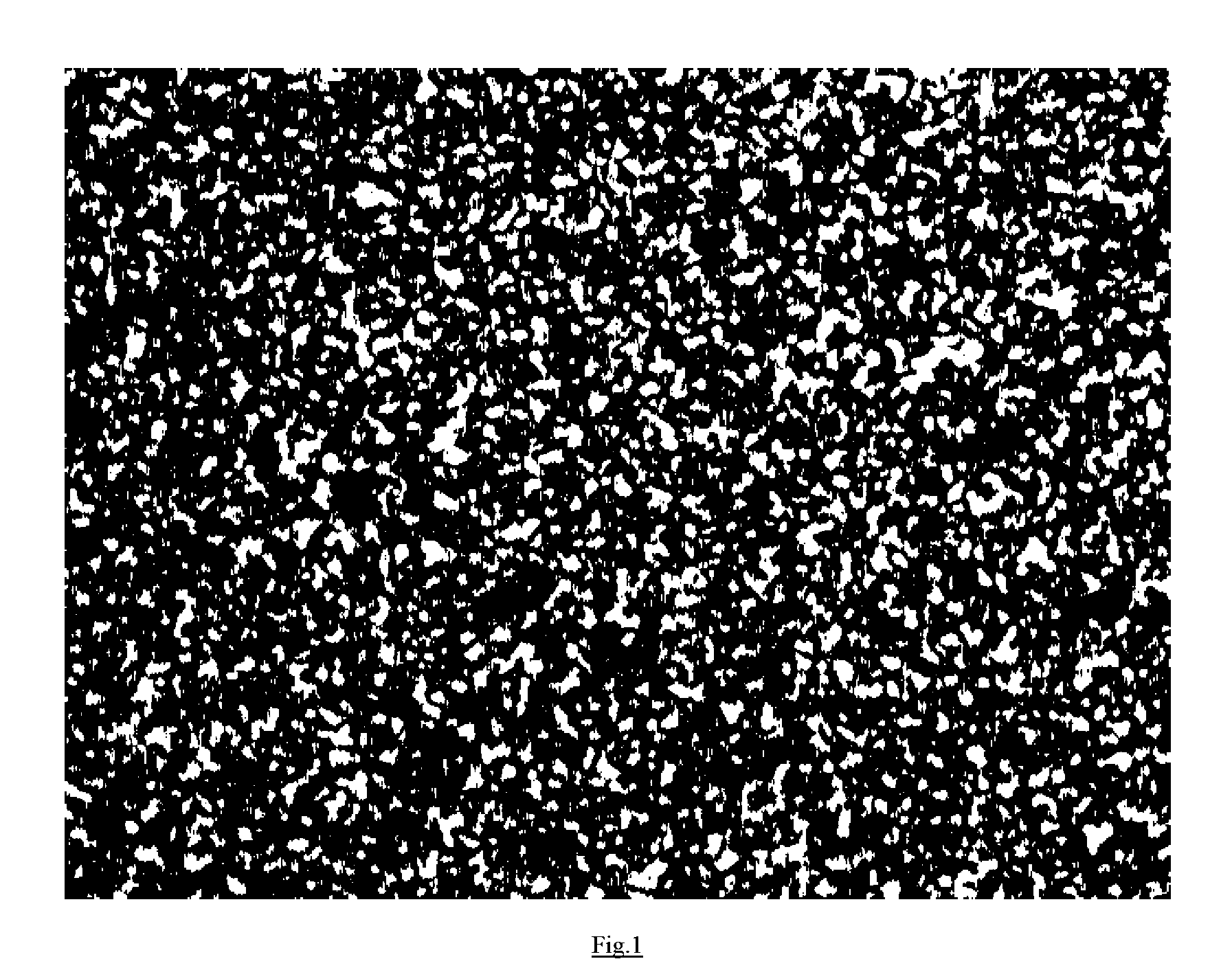
FIG. 1 shows a speckle pattern generated from a coherent source of radiation, such as light from a laser, scattering off a rough surface. The dark regions correspond with destructive interference and the bright spots correspond with constructive interference effects.

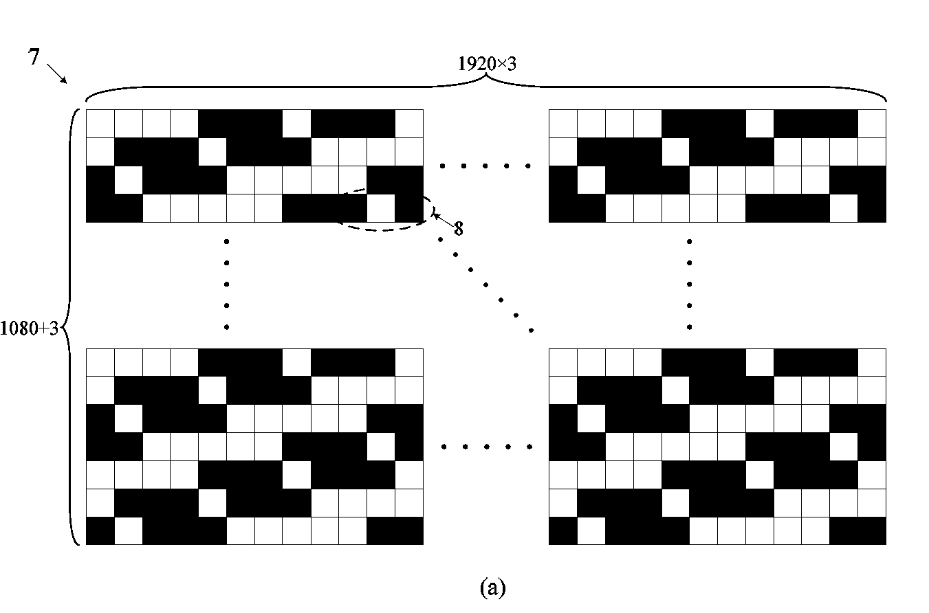
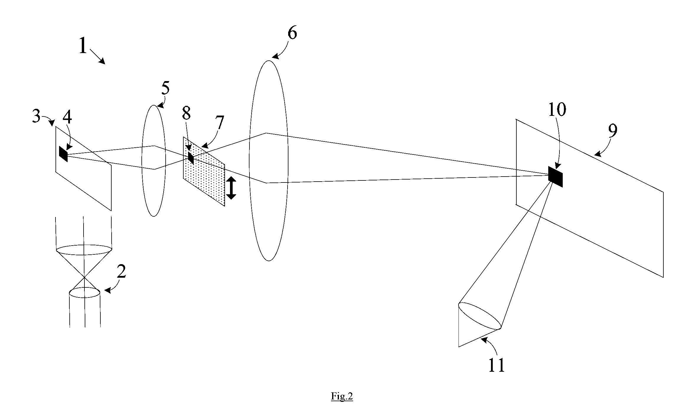
FIG. 2 shows a display system 1 that includes a phase diffuser at an intermediate image plane of a projection lens 5, 6 (acting as a beam expander). The display system 1 shown in FIG. 2 may include a laser source 2, a digital micromirror device (DMD) 3, which acts as a light modulator, a screen 9 and a detector 11. The phase diffuser or speckle reduction mask 7 may be in the form of a binary phase mask in configured as an orthogonal array (OA) having parameters N1, N2, s and t, where N1 represents runs, N2 represents factors, s represents levels and t represents strength. When a monochromatic laser is expanded and illuminated at the DMD chip 3, a full frame monochromatic image may be formed on the phase diffuser or speck...


PUM

PropertyMeasurementUnit
angleaaaaaaaaaa
angleaaaaaaaaaa
angleaaaaaaaaaa

Abstract

Speckle reduction apparatus includes a radiation path and a mask arranged within the radiation path. The mask includes an array of electrically controllable cells configured to form a pattern on the mask that varies with time. The speckle reduction mask includes a first linear array including first parallel lines arranged to change the phase of incident radiation, and a second linear array including second parallel lines arranged to change the phase of incident radiation and further arranged such that cells are formed at the intersections of the first parallel lines and the second parallel lines. The speckle reduction mask includes a N1×N2 array of cells, A, formed according to:
ATA=βδk,l,
where AT is the transpose of A, β is a real and positive constant, dk,l is Kronecker delta and N1≠N2.

Description

CROSS REFERENCE TO RELATED APPLICATIONThis application claims the benefit under 35 USC 119 of U.K. Patent Application GB1003822.2 filed Mar. 8, 2010, the entire disclosure of which is incorporated herein by reference.FIELD OF THE INVENTIONThe presented invention relates to the reduction of speckle and especially for use with laser illumination, such as a laser display system.BACKGROUND OF THE INVENTIONSpeckle is induced by light interference emerging from a screen. As shown in FIG. 1, the presence of speckle results in a granular pattern and can mask image formation.The origin of this granular pattern is the extremely rough screen surface on the scale of the incident (e.g. optical) wavelength. Under illumination of coherent radiation, such as lasers, the wave reflected from such a surface consists of contributions from many independent scattering areas. Propagation of this reflected light to a distant observation point results in the addition of these various scattered components wi...

Claims


Application Information

Patent Timeline
Patent Type & Authority Applications(United States)
IPC IPC(8): G02B27/48G02F1/01
CPCG02F1/01G02B27/48G03H1/32G02B5/02G03F7/2008G03F7/70058G03F7/70116G03F7/70191G03F7/702G03F7/70258G03F7/70583G03F7/70758
Inventor TONG, ZHAOMINGAO, WENHONGCHEN, XUYUANAKRAM, MUHAMMAD NADEEMGUANGMIN, OUYANGWANG, KAIYING
Owner HGSKOLEN I BUSKERUD OG VESTFOLD
Why Eureka
Try Eureka