Video laryngoscope

a laryngoscope and video technology, applied in the field of video laryngoscopes, can solve the problems of increasing the overall size of the device, affecting the operation of the laryngoscope, and being difficult to manoeuvre than the traditional laryngoscope, so as to facilitate fine reduce the movement of the head, and increase the control of the laryngoscope manipulation.

Active Publication Date: 2016-06-14
COVIDIEN AG
View PDF15 Cites 5 Cited by
  • Summary
  • Abstract
  • Description
  • Claims
  • Application Information

AI Technical Summary

Benefits of technology

[0019]Display screens of known video laryngoscopes may be positioned to one side of the laryngoscope body or on the end of the laryngoscope body, so as to permit the best possible view of the patient's mouth cavity in use (and in some cases permit direct viewing of the patient's trachea, epiglottis or larynx), and so as to afford the user the maximum range of alternative hand positions about the grip and / or the body. Video laryngoscopes are also known having display screens positioned in front of the body, in line with the grip portion, so that the screen is in, or close to, the line of sight of the user when they are directly viewing, thus making alternating between direct and indirect views easier.
[0043]In some embodiments, the display screen assembly (and the display screen) is flexible (at least in part; typically, at least at its end furthest from the insertion section), so as to minimise possible obstruction by a patient's chin, neck, chest, clothing or other equipment or objects in the vicinity in the event that the display screen assembly is brought into contact therewith. The body may comprise a grip portion and the display screen may be flexible where it extends beyond the grip portion. The grip portion may be rigid. Thus, the screen may flex in use, for example, when it contacts a patient's body or other equipment or objects, beyond the rigid grip portion.

Problems solved by technology

A disadvantage of these arrangements is that the relatively high mass of the video screen and supporting electronics can provide a relatively large and bulky device in which the centre of gravity is out of the hand and which is harder to manoeuvre than traditional laryngoscopes.
This works well with the laterally offset blade of the laryngoscope but does increase the overall size of the device.
However, this design is impractical as it prevents a user from forming a good grip around the blade.

Method used


Image

  • Video laryngoscope
  • Video laryngoscope
  • Video laryngoscope

Examples


Embodiment Construction

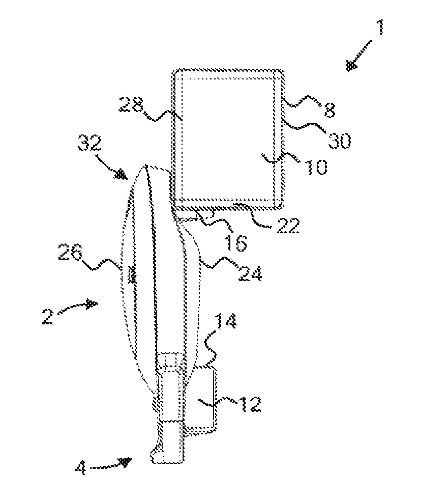
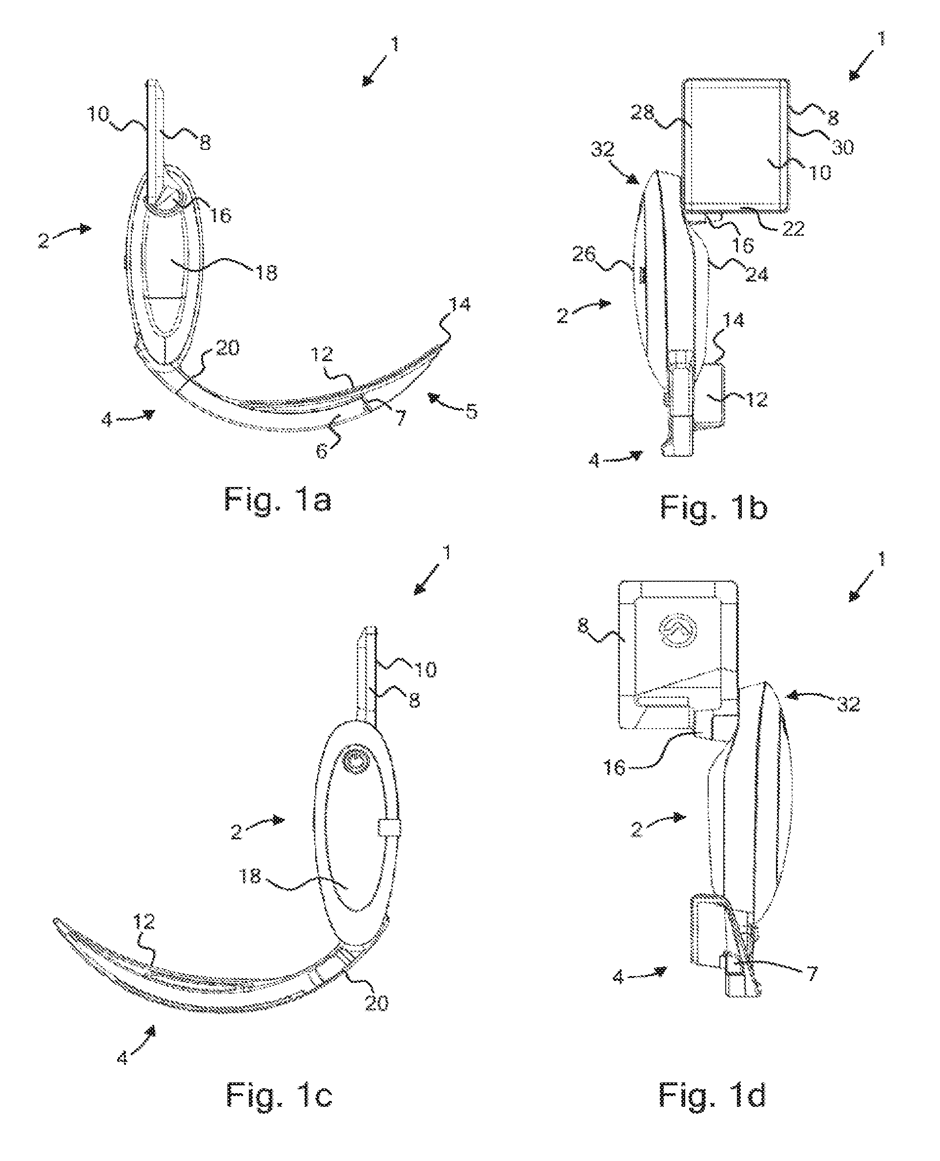
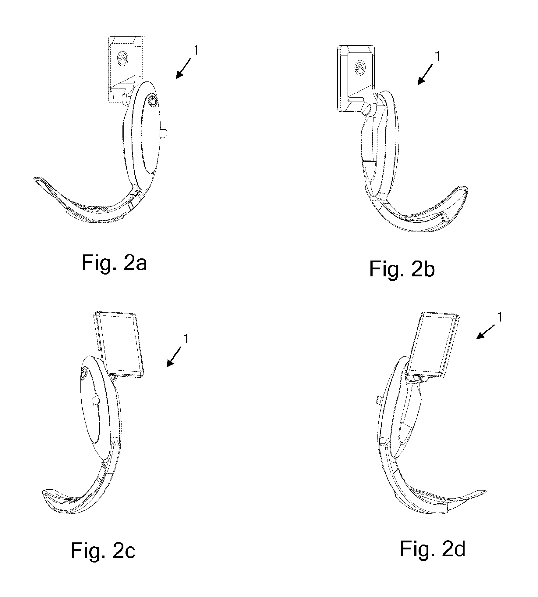
[0066]FIG. 1 shows a video laryngoscope 1 comprising a body 2 and an insertion section 4 extending from the body. A display screen assembly 8 is connected to the body comprises an LCD display screen 10 which is oriented generally perpendicular to the plane of the insertion section, as can be seen most clearly in FIGS. 1b and 1d.

[0067]The insertion section comprises a distal portion 5 for manipulating the tissues of a patient's trachea, epiglottis or larynx, and a camera element 6 extending through a channel in the insertion section to a lens 7. An image obtained by a camera at the distal end of the camera element, adjacent the lens, is operable to capture an image, to be displayed on the screen and thereby provide an indirect view of a patient's oral cavity (and in particular the epiglottis, trachea or larynx) in use.

[0068]The insertion section further comprises an inferior surface, which, in use, is engaged with a patient's tongue. The inferior surface of the embodiments shown is ...


PUM


Abstract

Disclosed is a video laryngoscope having a body, an insertion section extending from the body generally parallel to a median plane of the laryngoscope extending through the body, and a display screen assembly extending from the body generally perpendicular to the median plane, the body comprising a grip portion intermediate the display screen assembly and the insertion section. The display screen assembly, comprising a display screen, extends laterally from the body and the inner edge of the display screen falls within the lateral extent of the body. The grip portion is also of a minimum size to allow an adult to grip the laryngoscope, the hand abutting the screen assembly. Thus, the laryngoscope is of a minimum overall size, the screen is positioned as close as possible to the line of sight of a user directly viewing the distal end of the insertion section, during a medical procedure, facilitating the user alternating between direct and indirect viewing, whereas the screen does not prevent the user from manipulating the laryngoscope by applying thumb pressure to the body. The laryngoscope may optionally be provided with thumb operable controls on the body or the screen. The screen may be adjustable about an axis, and, by virtue of the configuration and size of the laryngoscope, adjustment may be effected by the user's thumb, without the need to adjust the grip of the remaining digits.

Description

[0001]This application is the U.S. national phase of International Application No. PCT / GB2010 / 051729, filed 13 Oct. 2010, which designated the U.S. and claims priority to GB Application No. 1008022.4, filed 13 May 2010, and GB Application No. 1016011.7, filed 23 Sep. 2010, the entire contents of each of which are hereby incorporated by reference.FIELD OF THE INVENTION[0002]The present invention relates to the field of video laryngoscopes having video screens which are either integral to, or demountably attachable to, the body of the video laryngoscope.BACKGROUND TO THE INVENTION[0003]Laryngoscopes have been in use for a very long period of time to enable a view to be obtained of the larynx, and to lift tissue adjacent to the epiglottis, or to lift the epiglottis directly, to enable an endotracheal tube to be inserted into a patient's trachea. The first laryngoscopes were direct laryngoscopes, enabling a user to obtain a direct line of sight to the patient's trachea, and direct laryn...

Claims


Application Information

Patent Timeline
Patent Type & Authority Patents(United States)
IPC IPC(8): A61B1/267A61B1/00
CPCA61B1/00052A61B1/00066A61B1/267A61B1/04A61B1/05
Inventor MCGRATH, MATTHEW JOHN ROSS
Owner COVIDIEN AG
Why Eureka
Try Eureka