Rotary platform user interface

a technology for user interfaces and rotating platforms, applied in the field of user interfaces for monitoring and controlling rotating platforms, can solve problems such as information overload for operators

Active Publication Date: 2016-06-14
DELAVAL HLDG AB
View PDF17 Cites 0 Cited by
  • Summary
  • Abstract
  • Description
  • Claims
  • Application Information

AI Technical Summary

Benefits of technology

[0021]Advantageously, where it is desired to provide an optimised layout of the sub-locations for each cell position, the relative positions of the cell sub-locations may be derived from the angular position of the relevant cell about the periphery of the representation of said platform. In this way, all cells will always represent their displayed information in a convenient way, adapted to the particular cell in question. This aspect of the control system of the invention

Problems solved by technology

The previously suggested solutions for creating input/output controls for animals being milked in in

Method used


Image

  • Rotary platform user interface
  • Rotary platform user interface
  • Rotary platform user interface

Examples


Embodiment Construction

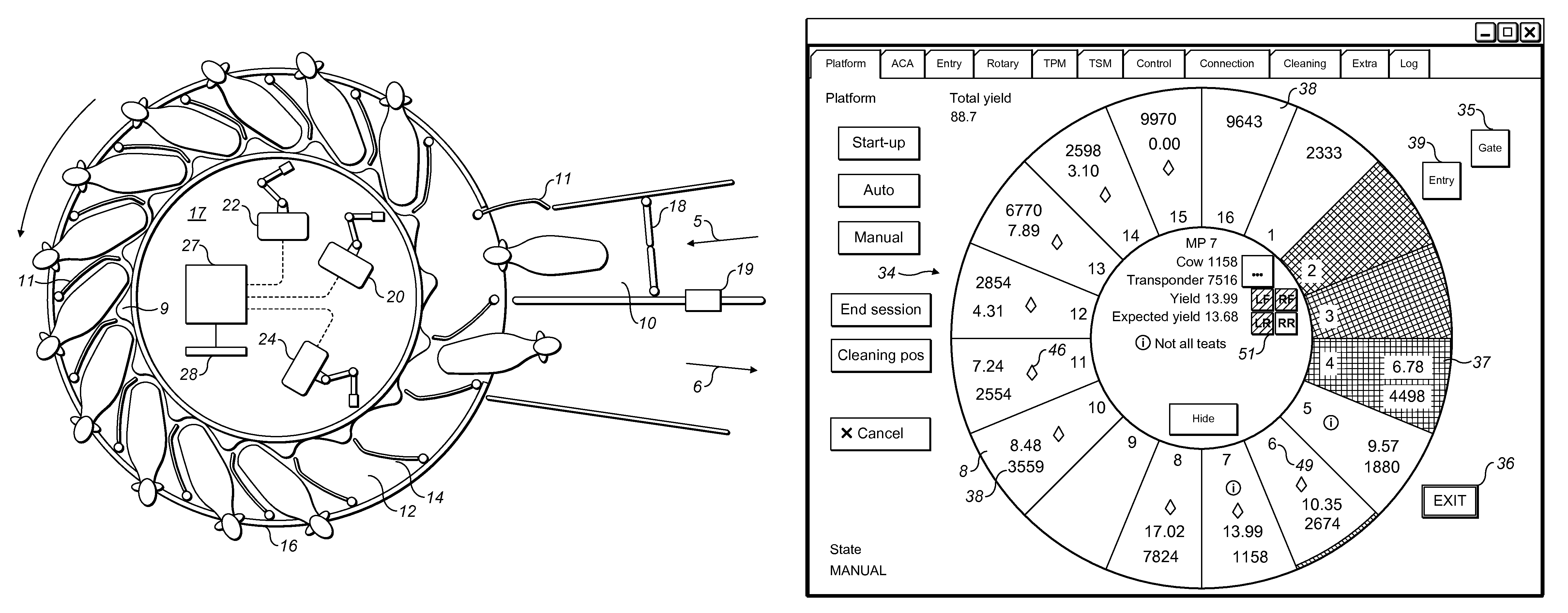
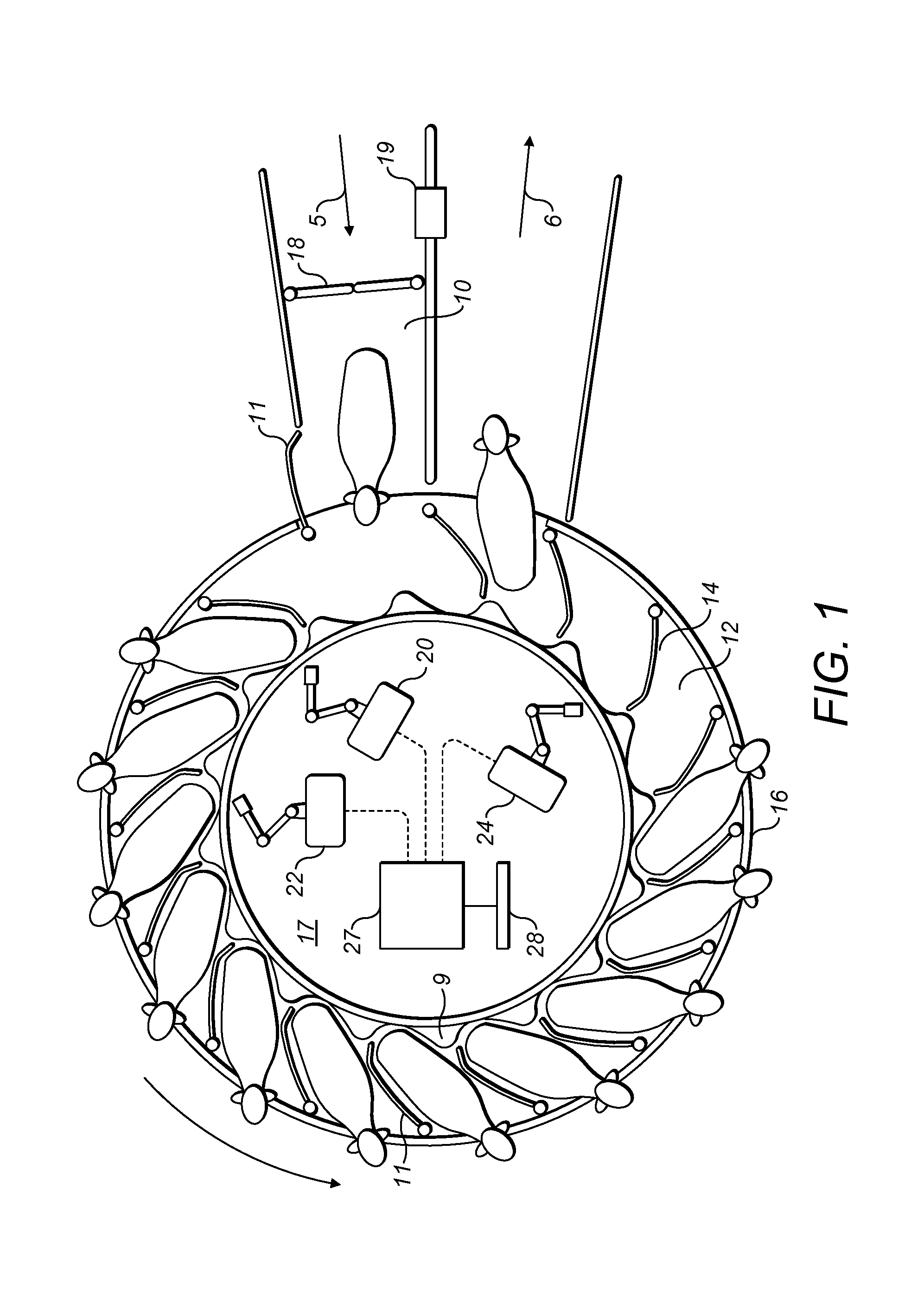
[0033]The animal management platform which is shown in FIG. 1 comprises a rotary platform 14 surrounded on its outer circumference by a barrier 16. The illustrated barrier 16 is a stationary barrier which is interrupted at an entrance area 5 and an exit area 6. More entrance or exit areas could be provided as a matter of choice. Alternatively, the entrance or exit areas could be configured larger than illustrated in order to allow, for example more than one animal to access or leave the platform simultaneously. In another alternative arrangement, the barrier 16 could be movable around the external circumference of the platform 14 and could be articulated at each stall for permitting opening and closing of the stall thereby allowing animals to enter or leave a stall. An internal perimeter of the platform 14 in the form of a railing 9 prevents animals from leaving the platform in a direction towards its centre. In certain embodiments, a feed manger (not shown) may be provided in each ...


PUM


Abstract

A control and monitoring system for a rotating animal platform which includes multiple animal stalls arranged about its periphery, where the system includes an interactive display screen which displays output information relating to the current status of operations on the platform and which displays input channels for use by an operator, the platform itself is represented at said interactive display screen by an annular shape, each stall on the platform is graphically represented by a cell, the cells are displayed in a spatial arrangement corresponding to the arrangement of stalls on the platform, real-time status information relating to operations on the platform is represented at each cell, and the rotating movement of the platform is represented by the progression of each cell about the displayed representation of the platform.

Description

BACKGROUND OF THE INVENTION[0001]1. Field of the Invention[0002]The present invention relates to a user interface for monitoring and controlling a rotating platform comprising multiple animal stalls. In particular, the present invention relates to the control and monitoring of dairy milking operations in an installation comprising multiple milking stalls on a rotating platform.[0003]The keeping of animals in installations in an industrial establishment has been transformed by the advent and expanded use of information technology. As a consequence, the control of animal related processes has developed such that a great many parameters relating to equipment can be controlled accurately and rapidly. In addition, the amount of information which is gathered concerning individual animals and parameters relating to their management has greatly increased. It has thereby resulted that control and management systems have become increasingly complex, both in terms of the variety of information...

Claims


Application Information

Patent Timeline
IPC IPC(8): A01K1/12A01J5/007G06Q50/02
CPCA01J5/007A01K1/126G06Q50/02G06T11/60A01J5/003A01J5/017A01K1/123A01K11/006
Inventor NYBERG, ANDERS
Owner DELAVAL HLDG AB
Why Eureka
Try Eureka