
Rotating animal milking platform control and monitoring system

a technology of monitoring system and rotating platform, which is applied in the direction of data processing applications, instruments, editing/combining figures or text, etc., can solve problems such as operator information overload

Active Publication Date: 2016-09-22
DELAVAL HLDG AB
View PDF3 Cites 0 Cited by
  • Summary
  • Abstract
  • Description
  • Claims
  • Application Information

AI Technical Summary

Benefits of technology

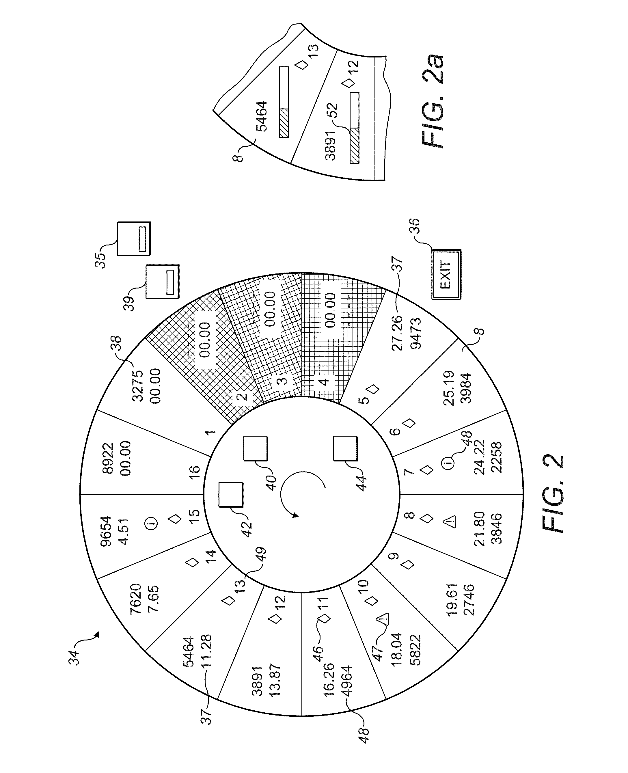
[0014]Accordingly, during use of the system of the invention, an operator supervising the activities on an animal platform will at all times during operation of the platform have a correspondence between the control system display and the current position of all the stalls on the platform, allowing the operator to easily and quickly monitor the progress of any and each of the contemporaneous operations in the respective stalls on the platform. The displayed information in each cell will provide a quick and ready reference for an operator, allowing any anomaly in the running of an operation to be spotted and acted upon. If necessary, the operator can use an input channel for adjusting information or parameters in any stall or robotic unit in order to modify current data relating to a particular operation or in order to make changes to operating parameters. At all times, the operator will be able to maintain a correspondence between the cell upon which adjustments are being made and the animal occupying the corresponding platform stall, thereby ensuring the best possible effectiveness during operation. This aspect may be of particular importance having regard to e.g. safety issues, for example, when an agitated animal is observed, its stall control location can be immediately found. Or, where an animal's current exhibited performance characteristics in a given cell appear out of the ordinary, then the animal can easily be seen at its corresponding location on the platform so that a rapid resolution of a possible problem can be facilitated. In all cases, the high level of correspondence between the displayed graphic image and the platform, as well as the simplified information display allows fast, safe, accurate and effective monitoring and control.
[0016]In a further embodiment, each cell which is included in the graphical representation exhibits each process parameter at a respective discrete sub-location inside each cell. Each cell typically comprises an identical number of information sub-locations although this may not be immediately apparent from the cells themselves, because not all the information sub-locations may be occupied by a displayed piece of text or symbol or icon or text input prompt. As mentioned, a process parameter which is displayed in any cell may in particular be any piece of information relating to the stall which corresponds to the particular cell, such as the operation being carried out in the stall or the animal or equipment in the stall. In the case of a milking platform, a useful process parameter which may be exhibited is the animal identification number stored in a transponder which is worn by the animal. In the case of a cow, this may be the animal's cow number. In many cases, the animal also wears a visible physical record of its identification number. The correct identification of animals at the platform stall is important because it may be relevant for a teat cup application robot or a teat treatment robot such as a teat finding and preparation robot. When using a system according to the invention, an operator may observe that an incorrect identification number is entered in the system by comparing a number in a given displayed cell with the number worn on an animal at the corresponding platform stall. The constant correspondence between the position of a stall on the platform and its representation as a cell in a display makes it easier to spot any such discrepancies. A corrective measure could be taken by, e.g. selecting the alphanumeric transponder field in the relevant displayed cell and entering a corrected number.
[0021]Advantageously, where it is desired to provide an optimised layout of the sub-locations for each cell position, the relative positions of the cell sub-locations may be derived from the angular position of the relevant cell about the periphery of the representation of said platform. In this way, all cells will always represent their displayed information in a convenient way, adapted to the particular cell in question. This aspect of the control system of the invention allows a display to show representations of platforms having different numbers of animal stalls, without creating a layout problem in case the number of stalls is increased or decreased. In addition, this arrangement ensures that an appropriate cell layout is always preserved, irrespective of the angular increments through which the displayed cells are moved each time the representation is periodically updated in the display, to reflect a changed angular platform position.

Problems solved by technology

The previously suggested solutions for creating input / output controls for animals being milked in individual stalls would lead, in the case of a rotary stall, to an information overload for operators.

Method used


Image

  • Rotating animal milking platform control and monitoring system
  • Rotating animal milking platform control and monitoring system
  • Rotating animal milking platform control and monitoring system

Examples


Embodiment Construction

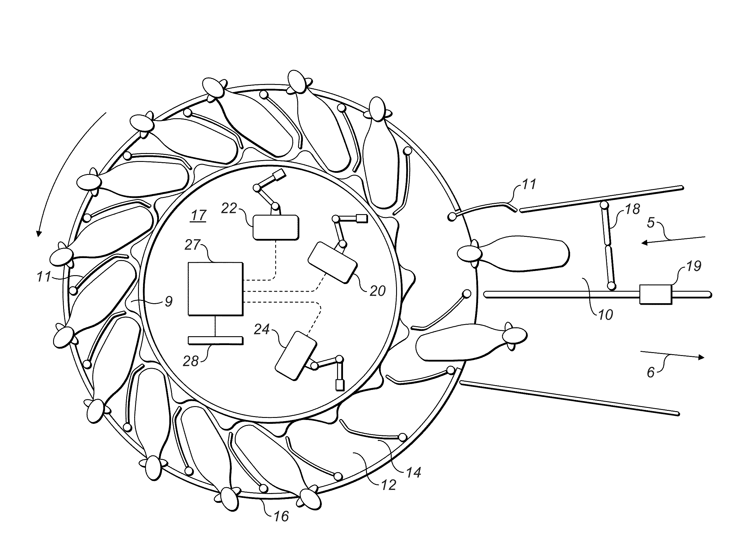
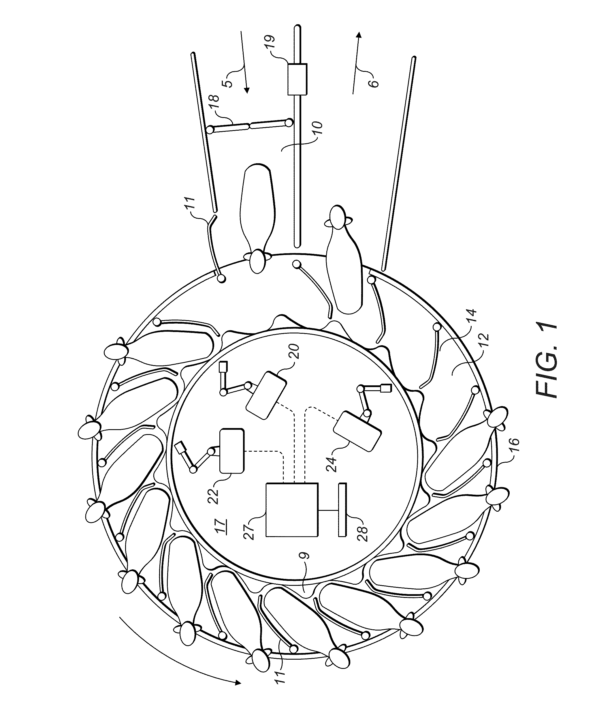
[0033]The animal management platform which is shown in FIG. 1 comprises a rotary platform 14 surrounded on its outer circumference by a barrier 16. The illustrated barrier 16 is a stationary barrier which is interrupted at an entrance area 5 and an exit area 6. More entrance or exit areas could be provided as a matter of choice. Alternatively, the entrance or exit areas could be configured larger than illustrated in order to allow, for example more than one animal to access or leave the platform simultaneously. In another alternative arrangement, the barrier 16 could be movable around the external circumference of the platform 14 and could be articulated at each stall for permitting opening and closing of the stall thereby allowing animals to enter or leave a stall. An internal perimeter of the platform 14 in the form of a railing 9 prevents animals from leaving the platform in a direction towards its centre. In certain embodiments, a feed manger (not shown) may be provided in each ...


PUM


Abstract

A control and monitoring system for a rotating animal platform which includes multiple animal stalls arranged about its periphery, where the system includes an interactive display screen which displays output information relating to the current status of operations on the platform and which displays input channels for use by an operator, the platform itself is represented at said interactive display screen by an annular shape, each stall on the platform is graphically represented by a cell, the cells are displayed in a spatial arrangement corresponding to the arrangement of stalls on the platform, real-time status information relating to operations on the platform is represented at each cell, and the rotating movement of the platform is represented by the progression of each cell about the displayed representation of the platform.

Description

BACKGROUND OF THE INVENTION[0001]1. Field of the Invention[0002]The present invention relates to a user interface for monitoring and controlling a rotating platform comprising multiple animal stalls. In particular, the present invention relates to the control and monitoring of dairy milking operations in an installation comprising multiple milking stalls on a rotating platform.[0003]The keeping of animals in installations in an industrial establishment has been transformed by the advent and expanded use of information technology. As a consequence, the control of animal related processes has developed such that a great many parameters relating to equipment can be controlled accurately and rapidly. In addition, the amount of information which is gathered concerning individual animals and parameters relating to their management has greatly increased. It has thereby resulted that control and management systems have become increasingly complex, both in terms of the variety of information...

Claims


Application Information

Patent Timeline
Patent Type & Authority Applications(United States)
IPC IPC(8): A01J5/007A01J5/017A01K11/00A01K1/12A01J5/003G06Q50/02
CPCA01J5/007A01K1/123A01J5/017A01J5/003A01K11/006A01K1/126G06Q50/02G06T11/60
Inventor NYBERG, ANDERS
Owner DELAVAL HLDG AB
Learn More