
Shift control method for DCT vehicle

a technology of clutch transmission and shift control, which is applied in the direction of gearing control, gearing element, belt/chain/gearing, etc., can solve the problems of discomfort for drivers, inability to change between the shift stages disposed at the same input shaft, etc., to improve the acceleration performance of the vehicle, improve the value of the vehicle, and fast shift responsiveness

Active Publication Date: 2016-06-21
HYUNDAI MOTOR CO LTD +1
View PDF12 Cites 0 Cited by
  • Summary
  • Abstract
  • Description
  • Claims
  • Application Information

AI Technical Summary

Benefits of technology

[0011]Accordingly, the present invention has been made keeping in mind the above problems occurring in the related art and / or other problems, and the present invention is intended to provide a shift control method for a dual clutch transmission (DCT) vehicle capable of securing fast shift responsiveness to meet the demands of a driver in a power-on downshift condition where the driver of the DCT vehicle steps an accelerator pedal to downshift to a lower shift stage, improving acceleration performance of the vehicle and therefore satisfaction of a driver, and ultimately contributing to improving the value of the vehicle.
[0014]According to the present invention, the shift control method for a DCT vehicle makes it possible to secure fast shift responsiveness to thus meet the demands of a driver in a power-on downshift condition where the driver of the DCT vehicle steps an accelerator pedal to downshift to a lower shift stage, to improve acceleration performance of the vehicle and therefore satisfaction of a driver, and to ultimately contribute to improving the value of the vehicle.

Problems solved by technology

However, in the DCTs, a change between the shift stages disposed at the same input shaft is impossible in the way as described above.
This may affect acceleration and shift performance of the vehicle, thus causing discomfort to the driver.

Method used


Image

  • Shift control method for DCT vehicle
  • Shift control method for DCT vehicle

Examples


Embodiment Construction

[0018]Reference will now be made in detail to various embodiments of the present invention(s), examples of which are illustrated in the accompanying drawings and described below. While the invention(s) will be described in conjunction with exemplary embodiments, it will be understood that present description is not intended to limit the invention(s) to those exemplary embodiments. On the contrary, the invention(s) is / are intended to cover not only the exemplary embodiments, but also various alternatives, modifications, equivalents and other embodiments, which may be included within the spirit and scope of the invention as defined by the appended claims.

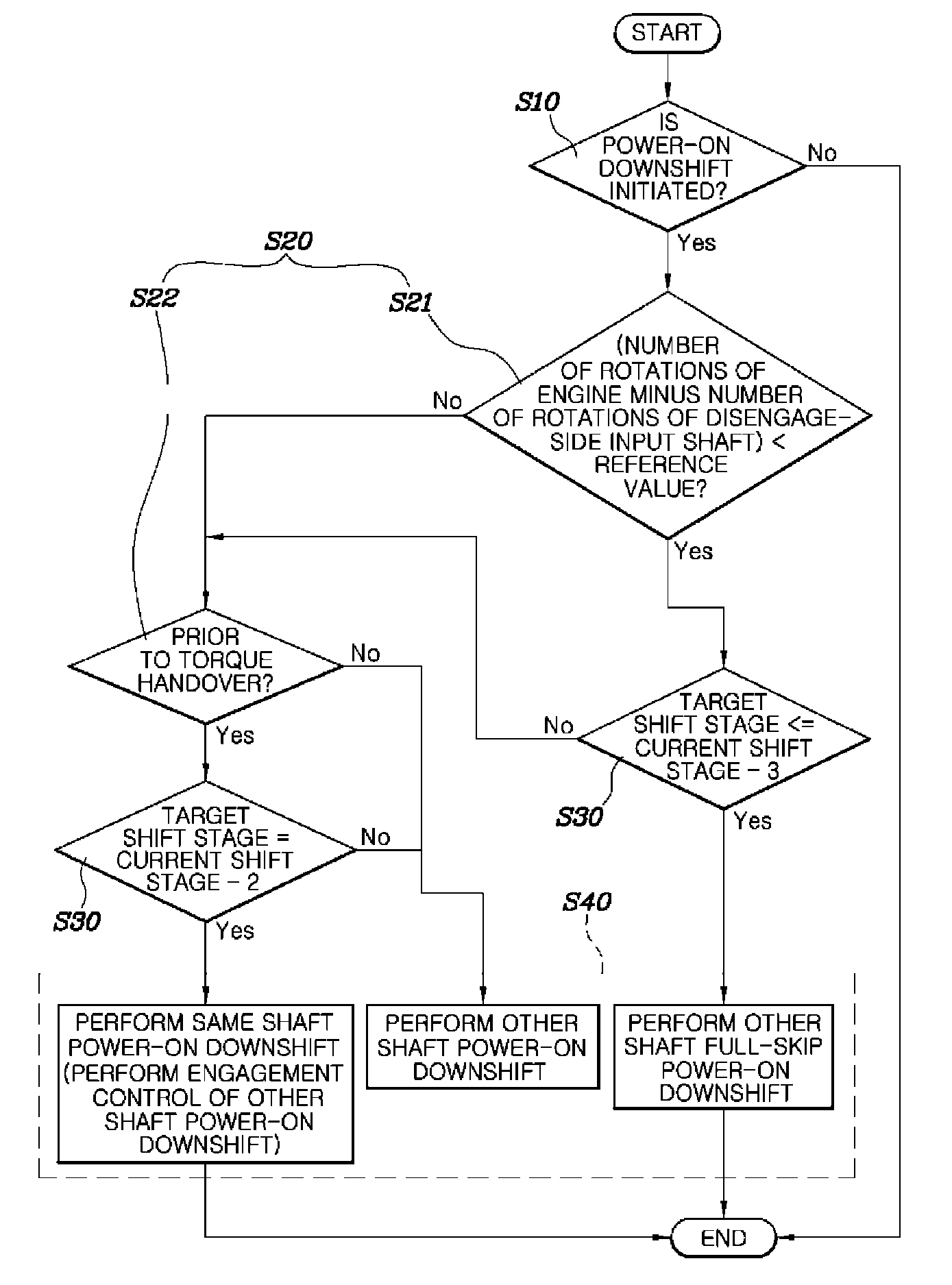
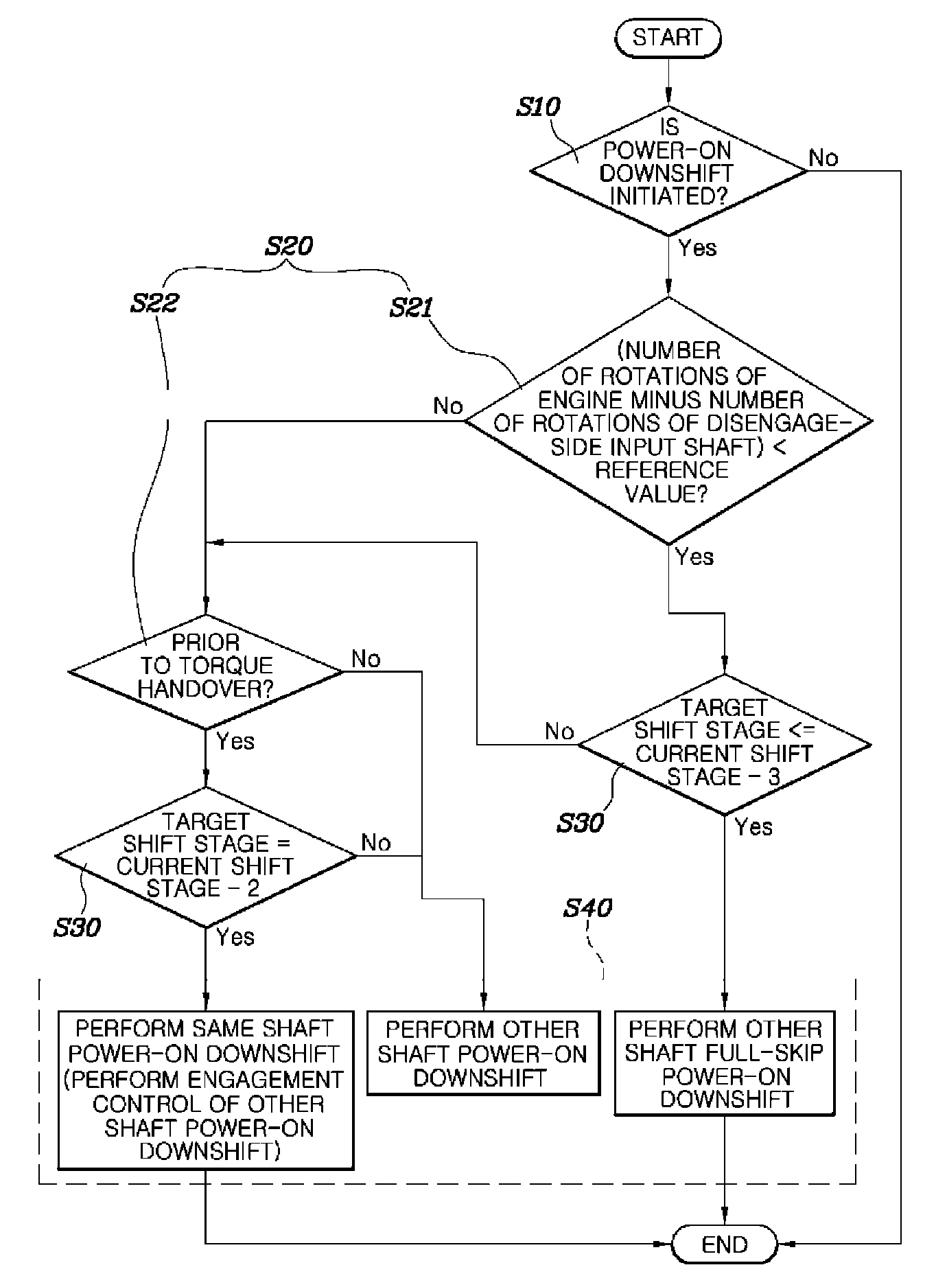
[0019]Referring to FIG. 1, a shift control method for a dual clutch transmission (DCT) vehicle according to various embodiments of the present invention includes: an initiation determining step S10 of determining whether power-on downshift is initiated; a progress determining step S20 of determining a progress degree of a shift proces...


PUM


Abstract

A shift control method for a dual clutch transmission (DCT) vehicle may include determining whether power-on downshift is initiated, determining a progress degree of a shift process if the power-on downshift is initiated, determining a difference in the number of shift stages between a target shift stage and a current shift stage according to the determined progress degree of the shift process, and selecting and performing one of downshifts (e.g., other shaft full-skip power-on downshift, same shaft power-on downshift, and other shaft power-on downshift) according to the progress degree of the shift process and the shift stage number difference.

Description

CROSS REFERENCE TO RELATED APPLICATION(S)[0001]The present application claims priority of Korean Patent Application Number 102014-0052141, filed on Apr. 30, 2014, the entire contents of which application are incorporated herein for all purposes by this reference.BACKGROUND OF INVENTION[0002]1. Field of Invention[0003]The present invention relates, in general, to a shift control method for a dual clutch transmission (DCT) vehicle and, more particularly, to a technique for making it possible to secure fast shift responsiveness according to vehicle operation of a driver.[0004]2. Description of Related Art[0005]Dual clutch transmissions (DCTs) are designed to provide two input shafts connected to two respective clutches, to dispose shift stage gears installed on the two input shafts with the shift stage gears divided into odd and even number sides, and to functionally distinguish the two input shafts such that one of the two shafts is used for the odd number stages and the other is used...

Claims


Application Information

Patent Timeline
Patent Type & Authority Patents(United States)
IPC IPC(8): F16H61/04F16H61/02F16H61/688
CPCF16H61/0213F16H61/02F16H61/04F16H61/688F16H61/0403F16H2061/0444Y10T477/688Y10T477/693Y10T477/6931Y10T477/6933F16H2306/00B60W10/02B60W10/113F16H59/66F16H61/00
Inventor CHO, SUNG HYUN
Owner HYUNDAI MOTOR CO LTD
Learn More