Detection method of current sensor faults in the e-drive system by using the voltage command error

a current sensor and e-drive technology, applied in the direction of electric motor control, control systems, instruments, etc., can solve the problems of increasing system cost, reducing overall system reliability, and not having a consistent approach to determining the threshold for checksum comparison

Active Publication Date: 2016-06-21
FORD GLOBAL TECH LLC
View PDF8 Cites 12 Cited by
  • Summary
  • Abstract
  • Description
  • Claims
  • Application Information

AI Technical Summary

Problems solved by technology

While the checksum algorithm is designed to detect an error in torque control that leads to an unintentional torque delivery, in many cases it is relied on as a means for detecting a current sensor fault, since most, if not all, field-oriented control systems lack a dedicated fault diagnostic for a current sensor.
However, several problematic issues are associated with the use of a checksum method for sensor fault detection.
For instance, there is no consistent approach for determining a threshold for the checksum comparison.
Several factors can affect threshold determination, including sensor accuracy, signal noise level and the sensor current range, so a threshold can be sensor and application specific, and its determination can necessitate a time-consuming calibration process.
When the vehicle drive system includes both a traction motor and a generator, two additional components are added, with each additional component increasing system cost while decreasing overall system reliability.

Method used


Image

  • Detection method of current sensor faults in the e-drive system by using the voltage command error
  • Detection method of current sensor faults in the e-drive system by using the voltage command error
  • Detection method of current sensor faults in the e-drive system by using the voltage command error

Examples


Embodiment Construction

[0020]Example embodiments of the invention are presented herein; however, the invention may be embodied in a variety of alternative forms, as will be apparent to those skilled in the art. To facilitate understanding of the invention, and provide a basis for the claims, various figures are included in the specification. The figures are not drawn to scale and related elements may be omitted so as to emphasize the novel features of the invention. Structural and functional details depicted in the figures are provided for the purpose of teaching the practice of the invention to those skilled in the art and are not to be interpreted as limitations. For example, modules and controllers for systems can be variously arranged and / or combined and may not be depicted in illustrations of example embodiments herein in order to better emphasize novel aspects of the invention. In addition, system components can be variously arranged as known in the art.

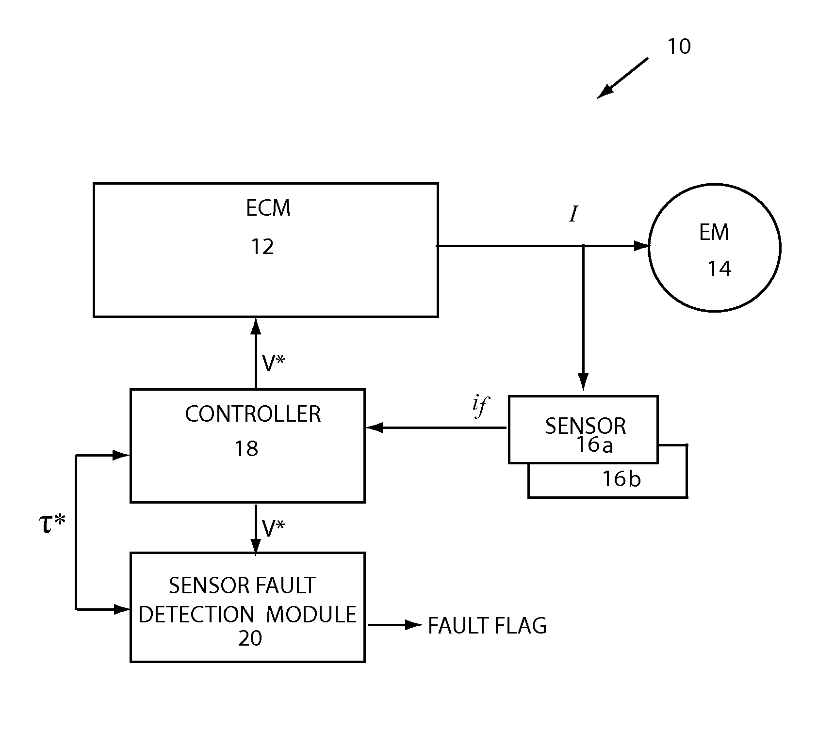
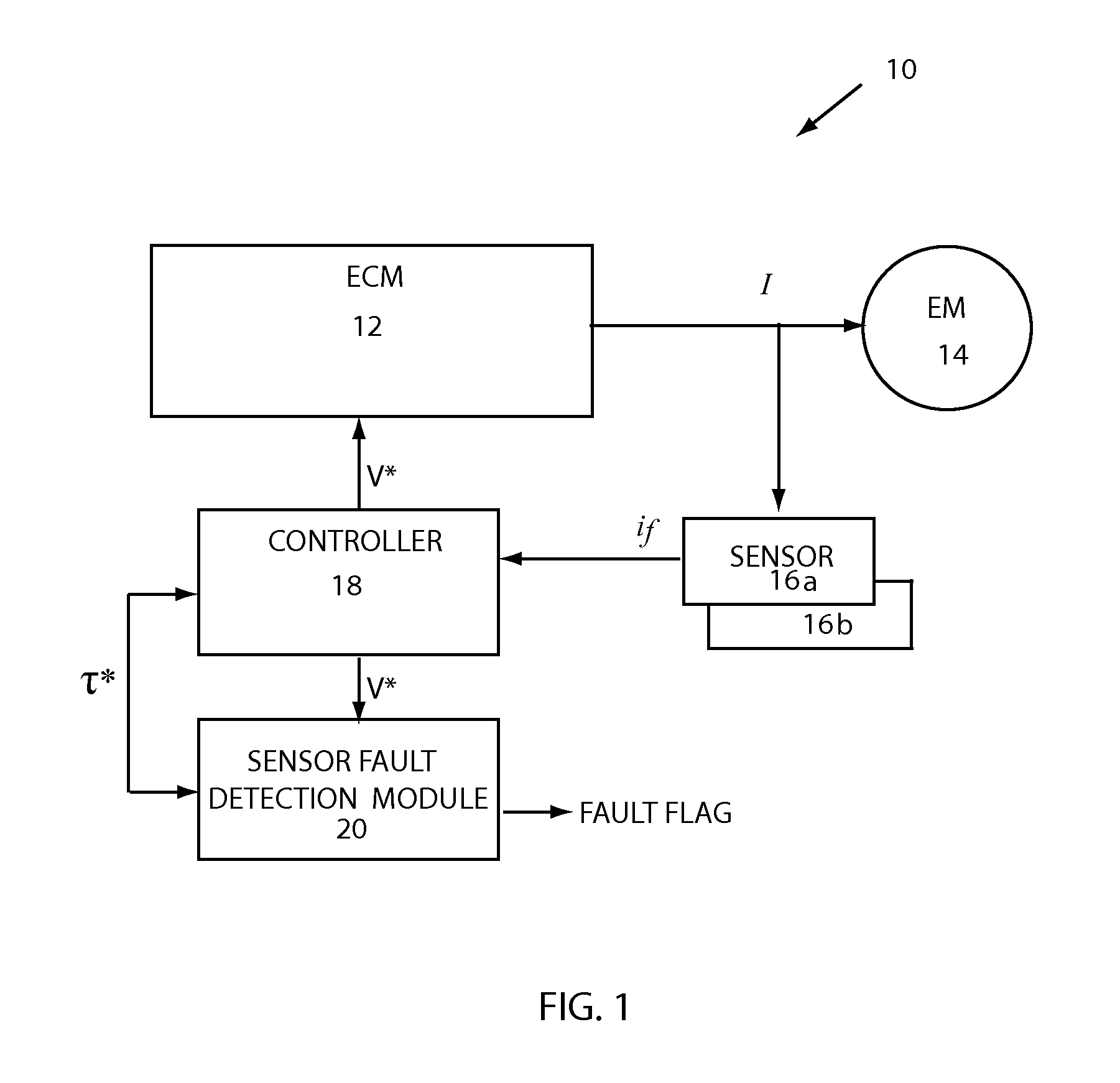
[0021]FIG. 1 shows an electric machine system ...


PUM


Abstract

Systems, apparatus, and methods detect a current sensor error in an FOC electric machine system. A voltage command is monitored to detect the presence of an ac component that indicates that an error has occurred at a current sensor. For example, a sensor fault detection module can be configured to determine the deviation between an actual voltage command and an ideal voltage command to provide a complex deviation vector. By transforming the deviation vector to a reference frame rotating at the fundamental frequency of the command voltage, a dc component of the positive and negative sequences can be filtered, and their amplitudes determined. Error detection can be based on the total amplitude of the fundamental component, determined by positive and negative component amplitudes. Sensor error detection enables an FOC system to operate with two current sensors, rather than three, and provides a dedicated fault diagnostic for a current sensor.

Description

FIELD OF INVENTION[0001]This invention relates generally to electronic drive system diagnostics, and more particularly to fault detection for current sensors used for field-oriented machine control.BACKGROUND OF INVENTION[0002]Electric machines can be used to provide torque for various types of systems, such as, but not limited to, electric drive systems for electrified vehicles in which machine-generated torque is used for vehicle propulsion. Electric drive systems often rely on field-oriented techniques to control machine operation and torque output. Field-oriented control requires feedback current to be provided to a machine controller so that a determination can be made as to whether torque output needs to be adjusted, and any required adjustment can be performed. Accordingly, several current sensors are disposed to detect current and provide the necessary feedback. In a typical arrangement, two current sensors are used specifically for torque control, and a third current sensor...

Claims


Application Information

Patent Timeline
Patent Type & Authority Patents(United States)
IPC IPC(8): G01R31/319H02P29/02
CPCG01R31/3191H02P29/0241H02P29/024
Inventor WANG, CHANG-JIANGDEGNER, MICHAELISAYEVA, RIMMAXU, LIWENLUEDTKE, DANIEL R.
Owner FORD GLOBAL TECH LLC
Why Eureka
Try Eureka