Direction restricting device for the inner and outer tubes of a bicycle seat post

a technology for restricting devices and bicycle seats, which is applied in the direction of rod connections, fastening means, cycle equipments, etc., can solve the problems of deflection and wobbling of tubes, varied height of needle bearings, etc., and achieves the effects of preventing deflection and wobbling of inner tubes, preventing deflection and wobbling, and strengthening the steadyness of both tubes

Active Publication Date: 2016-06-28
TAIWAN HODAKA INDAL
View PDF25 Cites 6 Cited by
  • Summary
  • Abstract
  • Description
  • Claims
  • Application Information

AI Technical Summary

Benefits of technology

[0006]It is a primary object of the present invention to provide a direction restricting device for the inner and outer tubes of a bicycle seat post that may not only restrict the axial movement of the inner tube but also eliminate the rotary interspace between the inner tube and the outer tube of a bicycle seat post to prevent deflection and wobble of the inner and outer tubes when they rotate relative to each other.
[0007]The present invention is characterized in that the direction restricting device includes at least one axial groove arranged on the wall of one of the inner and outer tubes, and a direction restricting element fastened to the other tube at the position relative to the axial groove wall. Said direction restricting element may be inserted into the axial groove and at least includes an elastic slider provided with an axial opening in the middle. The direction restricting element may be inserted into the axial groove to enable the axial outer walls of the direction restricting element to engage with the axial inner walls of the axial groove to eliminate the interspace between the slider and the axial groove to prevent deflection and wobbling and to reinforce the steadiness of both tubes when the inner and outer tubes rotate relative to each other.

Problems solved by technology

However, the height of the needle bearings may become varied after operating for a long time.
In addition, an interspace occurs between the axial walls of the aforesaid opposing flats between the outer tube and the inner tube, and said interspace may cause deflection and wobbling of the tubes when the inner and outer tubes rotate.

Method used


Image

  • Direction restricting device for the inner and outer tubes of a bicycle seat post
  • Direction restricting device for the inner and outer tubes of a bicycle seat post
  • Direction restricting device for the inner and outer tubes of a bicycle seat post

Examples


Embodiment Construction

[0028]The means for achieving the aforesaid objective and the functions of the present invention will become apparent from the following description, taken in connection with the accompanying drawings, wherein a preferred embodiment of the present invention is disclosed.

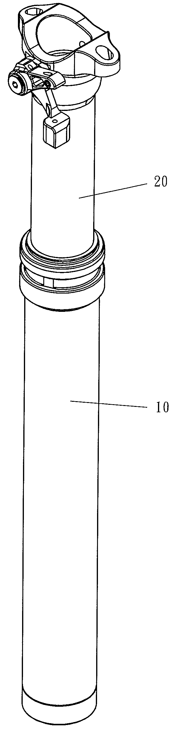
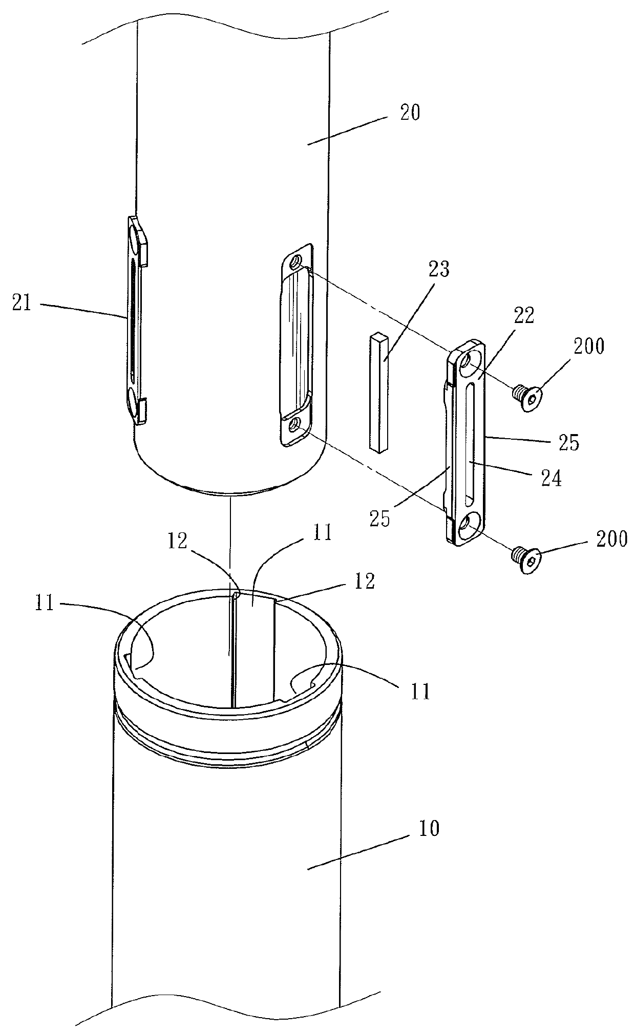
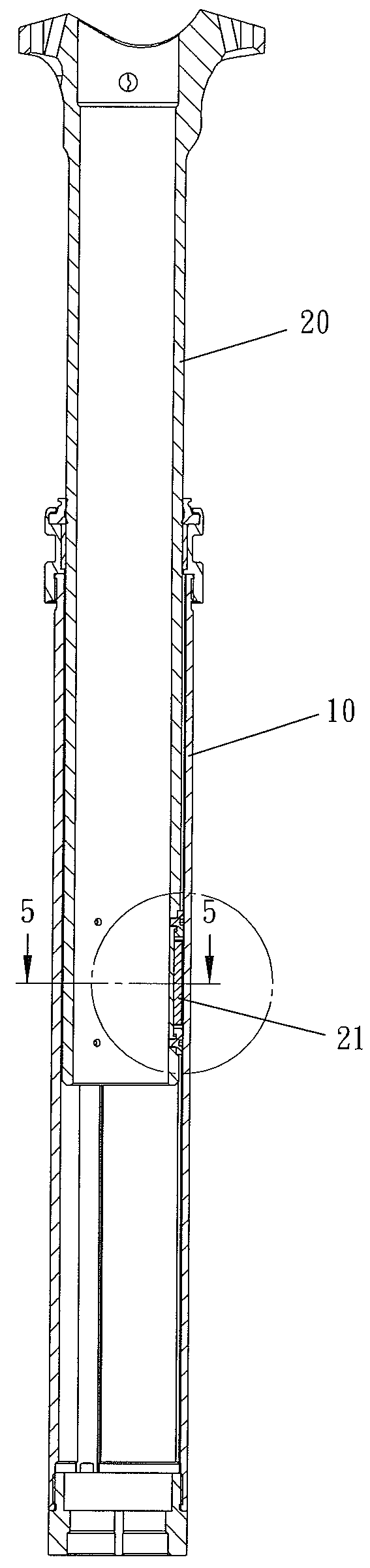
[0029]Referring to FIG. 1 to FIG. 6, a first embodiment of the present invention comprises: an outer tube 10 having an internal wall which is provided with a plurality of axial grooves 11 spaced in equidistant arrangement, with two inner sides of said axial grooves 11 respectively disposed with an axial groove wall 12; and an inner tube 20 having an end inserted into said outer tube 10, provided with an outer wall, at the position relative to each axial groove 11 of said outer tube 10, and screwed respectively with a direction restricting element 21 by a screw piece 200. Said direction restricting element 21 protrudes from the outer wall of said inner tube 20 and is allowed to be inserted into the axial grooves 11 of...


PUM


Abstract

A direction restricting device, for the inner and outer tubes of a bicycle seat post, includes at least one axial groove arranged on the wall of one of the tubes, and a direction restricting element fastened to the other tube at the position relative to the axial groove wall. The direction restricting element may be inserted into the axial groove and at least includes an elastic slider provided with an axial opening in the middle. The direction restricting element may be inserted into the axial groove to enable the axial outer walls of the direction restricting element to engage with the axial inner walls of the axial groove to eliminate the interspace between the slider and the axial groove to prevent deflection and wobbling and to reinforce the steadiness of both tubes when the inner and outer tubes rotate relative to each other.

Description

BACKGROUND OF THE INVENTION[0001]1. Field of the Invention[0002]The present invention relates to a direction restricting device for the inner and outer tubes of a bicycle seat post and, more specifically, to a structure that may eliminate the rotary interspace between the inner tube and the outer tube of a bicycle seat post to prevent deflection and wobble when said inner and outer tubes rotate relative to each other.[0003]2. Description of the Prior Art[0004]The seat post is used for supporting the seat, and, normally, the seat post of a bicycle includes at least an outer tube and an inner tube joined to each other to adjust the seat height. In order to prevent the outer tube and the inner tube from rotating, generally, a direction restricting device is arranged between the inner and outer tubes to limit the inner tube to axial movements, such as the direction restricting arrangement of the bicycle suspension system disclosed in U.S. Pat. No. 6,145,862. According to FIG. 3B shown i...

Claims


Application Information

Patent Timeline
Patent Type & Authority Patents(United States)
IPC IPC(8): B25G3/02B62K19/36F16B7/10B62J1/08
CPCB62K19/36B62J1/08F16B7/10B62J2001/085Y10T403/7026
Inventor KUO, FRANK
Owner TAIWAN HODAKA INDAL
Why Eureka
Try Eureka