Transmitting-receiving-separated dual-polarization antenna

a dual-polarization antenna and transmission-receiving technology, applied in the direction of polarised antenna unit combinations, individually energised antenna arrays, resonant antennas, etc., can solve the problem of responding to the high required value, and achieve the effect of reducing the coupling between transmission and reception

Active Publication Date: 2016-06-28
DENKI KOGYO CO LTD +1
View PDF22 Cites 5 Cited by
  • Summary
  • Abstract
  • Description
  • Claims
  • Application Information

AI Technical Summary

Benefits of technology

[0019]According to the present invention, coupling between transmission and reception can be reduced while implementing sharing of polarized waves for both the transmitting band and the receiving band. For example, even in a case in which the element spacing among the patch antennas for the transmitting band and the patch antennas for the receiving band is set as narrow as 0.4λ0 (λ0 is a wavelength of the center frequency between a lower limit frequency for the receiving band and an upper limit frequency for the transmitting band), coupling between transmission and reception as low as −30 dB or lower can be implemented. In addition, according to the present invention, it is enabled to downsize a bandpass filter provided at a subsequent stage by omitting a diplexer which may otherwise be arranged inside a transmitting and receiving front end circuit.

Problems solved by technology

However, if the above-described configuration is applied to a frequency division duplex (FDD) system, a required value becomes high for the bandstop amount for signals in unnecessary frequency bands in order to separate signals in the transmitting band, and accordingly, a problem may arise such that it becomes necessary to respond to the high required value by using a multi-stage large diplexers and bandpass filters.

Method used


Image

  • Transmitting-receiving-separated dual-polarization antenna
  • Transmitting-receiving-separated dual-polarization antenna
  • Transmitting-receiving-separated dual-polarization antenna

Examples


Embodiment Construction

[0044]In the following description, f0 and λ0 are a center frequency between a lower limit frequency of the receiving band and an upper limit frequency of the transmitting band and a wavelength thereof, respectively, fR and λR are a center frequency of the receiving band and a wavelength thereof, respectively, fT and λT are a center frequency of the transmitting band and a wavelength thereof, respectively, and fR=0.953 f0 (wavelength λR=1.049λ0), fT=1.047 f0 (wavelength λT=0.955λ0).

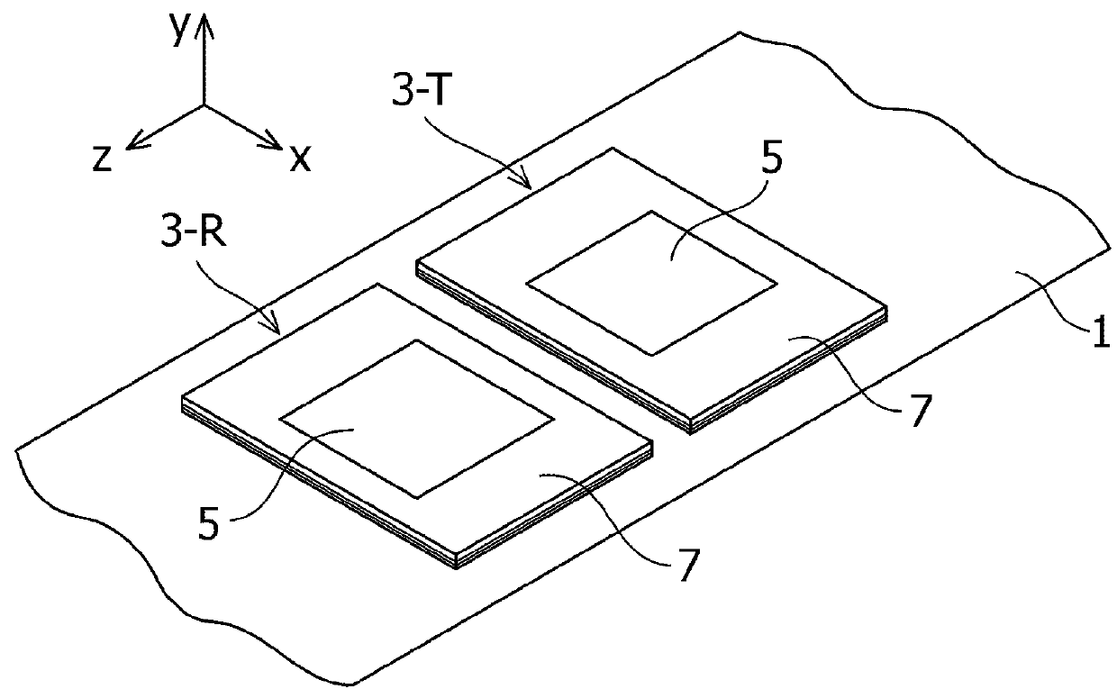
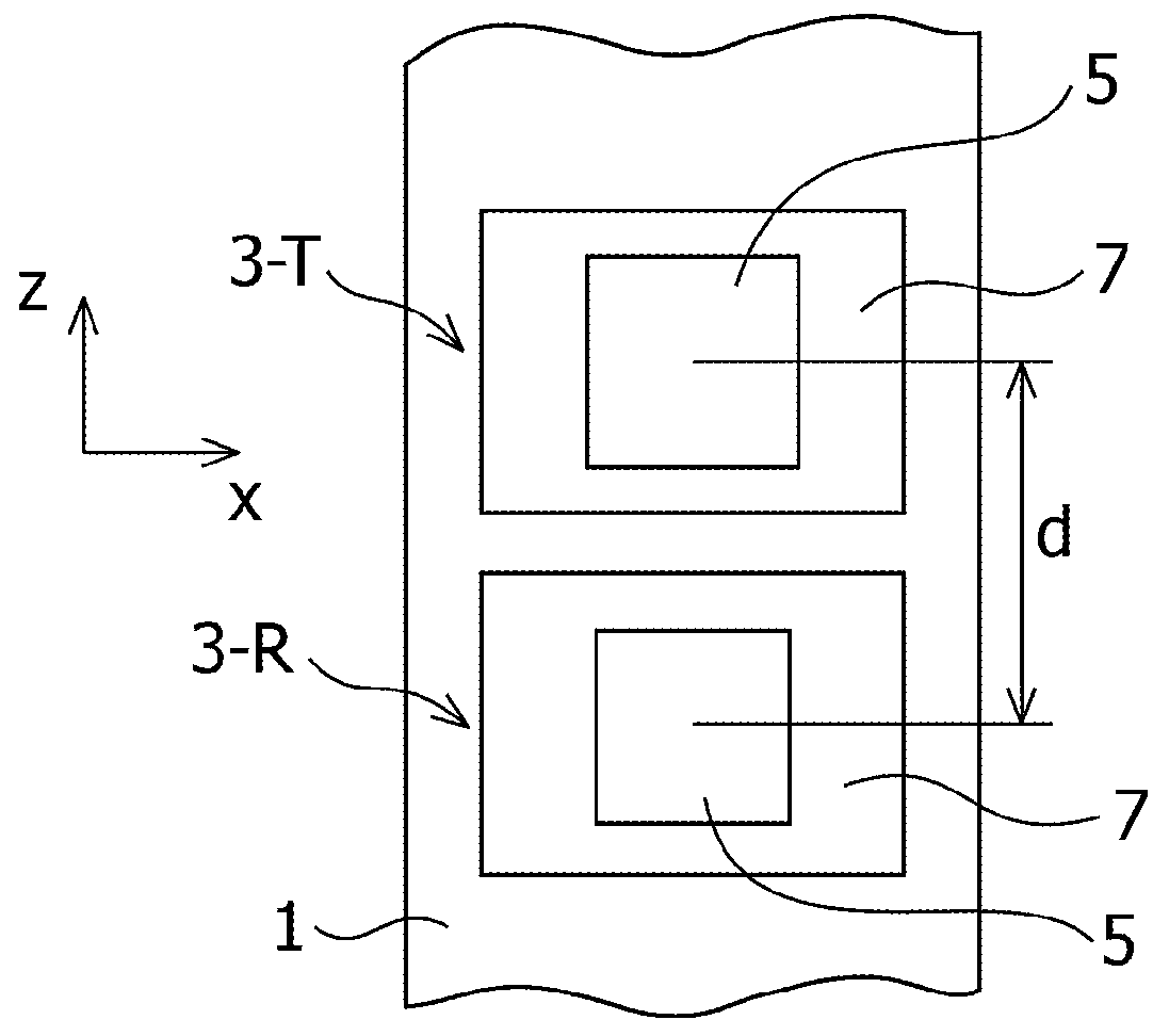
[0045]FIGS. 1 and 2 are a perspective view and a plan view which illustrate an embodiment of a transmitting-receiving-separated dual-polarization patch antenna according to the present invention. In these drawings, the direction of z-axis is perpendicular to the ground and the xy plane is a plane parallel to the ground. A transmitting-receiving-separated antenna according to the present embodiment includes a patch antenna 3-T for a transmitting band and a patch antenna 3-R for a receiving band, which are ...


PUM


Abstract

To reduce coupling between transmission and reception while implementing sharing of polarized waves for both the transmitting band and the receiving band at the same time. Patch antenna for transmitting band and patch antenna for receiving band, which are arranged at predetermined spacing, include an upper-stage ground conductor; a lower-stage ground conductor; a feed line which is arranged among the ground conductor and the lower-stage ground conductor; a feed slot which is formed on the upper-stage ground conductor; a patch which is electromagnetically coupled with the feed line via the feed slot; and electromagnetic shielding members which are connected with the upper-stage ground conductor and the lower-stage ground conductor in a state in which the electromagnetic shielding members are located around the feed line. The feed line includes independent feeding conductors corresponding to respective polarized waves.

Description

CROSS REFERENCE TO RELATED APPLICATIONS[0001]The present application is a national phase entry under 35 U.S.C. §371 of International Application No. PCT / JP2012 / 076199, filed Oct. 10, 2012, published in Japanese, which claims priority from Japanese Patent Application No. 2011-268961 filed Dec. 8, 2011, all of which are hereby incorporated herein by reference.TECHNICAL FIELD[0002]The present invention relates to a transmitting-receiving-separated dual-polarization antenna particularly preferable for use at a mobile communication base station.BACKGROUND ART[0003]In order to secure power per bit, which has been increasing as the data transmission speed becomes higher, it is useful to reduce the loss in a feed system (see Non-Patent Literature 1, for example). FIG. 20 illustrates a configuration in which a transmitting and receiving front end circuit and an antenna are integrally implemented, which is one of the means for implementing the reduction of loss in a feed system.[0004]In FIG. ...

Claims


Application Information

Patent Timeline
Patent Type & Authority Patents(United States)
IPC IPC(8): H01Q1/38H01Q9/04H01Q1/52H01Q21/24H01Q21/06H01Q1/24H01Q21/08
CPCH01Q1/525H01Q1/526H01Q9/0457H01Q21/065H01Q21/24H01Q1/246H01Q9/0435H01Q21/08
Inventor SATO, KEISUKENAKANO, MASAYUKIMATSUNO, HIROMI
Owner DENKI KOGYO CO LTD
Why Eureka
Try Eureka