Impact pad

a technology of impact pad and refractory shell, which is applied in the field of impact pad, can solve the problems of undue erosion of the refractory shell within the tundish, uneven flow of molten steel to the casting mould, and turbulence within the tundish itself, so as to reduce short-circuiting and increase the residence time

Active Publication Date: 2016-07-05
VESUVIUS USA CORP
View PDF11 Cites 0 Cited by
  • Summary
  • Abstract
  • Description
  • Claims
  • Application Information

AI Technical Summary

Benefits of technology

[0010]It is an object of the present invention to provide an improved impact pad suitable for placement in a tundish for increasing the residence time, inducing uniformity of residence time, and minimizing short-circuiting, of the flow of molten metal introduced therein.
[0032]Impact pads in accordance with the present invention can be used, for example, to provide reduced dead volume and / or improved plug flow and / or reduced turbulence in tundishes for holding molten steel.

Problems solved by technology

The stream of molten steel from the ladle generally enters the tundish with considerable force, and this can generate considerable turbulence within the tundish itself.
Any undue turbulence in the flow of molten steel through the tundish has a number of undesirable effects including, for example; preventing slag and other undesirable inclusions in the steel from agglomerating and floating to the surface; entraining into the molten steel a part of the protective crust that forms, or is specifically provided, on the surface of thereof; entraining gas into the molten steel; causing undue erosion of the refractory lining within the tundish; and generating an uneven flow of the molten steel to the casting mould.
It will be appreciated that the process of designing a new tundish impact pad which meets particular pre-determined criteria is extremely complex, since changing one aspect of the design of an impact pad generally has unforeseen ramifications on the flow dynamics of the entire tundish system.

Method used


Image

  • Impact pad
  • Impact pad
  • Impact pad

Examples


Embodiment Construction

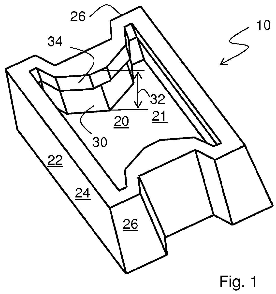
[0047]FIG. 1 shows an impact pad 10 comprising a base 20 having an impact surface 21 facing upwards towards an interior, and a wall 22 extending upwardly from base 20. The wall 22 has a longitudinal portion 24 and a latitudinal portion 26. A protrusion 30 extends inwardly, towards the center of the impact pad, from latitudinal portion 26. Protrusion height 32 is the distance between the impact pad impact surface 21 and the top of protrusion 30. Overhang 34 extends horizontally inwards from the top of wall 22.

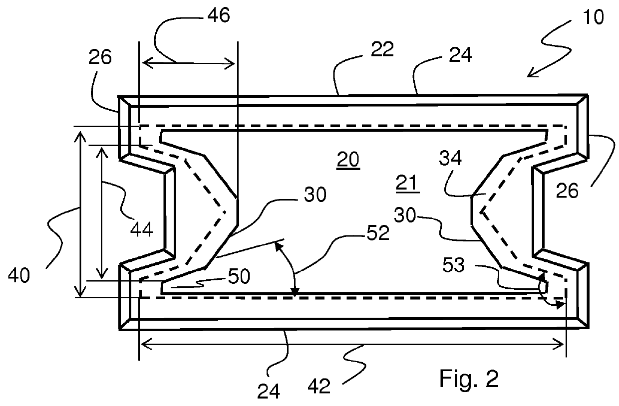
[0048]FIG. 2 shows a plan view of an impact pad 10 of the present invention. Base 20 has an impact surface 21; wall 22 extends from the impact surface 21. Wall 22 is composed of longitudinal portions 24 and latitudinal portions 26. A pair of protrusions 30 extends inwardly, towards the center of the impact pad, each from latitudinal portions 26. Overhang 34 extends horizontally inwards from the top of wall 22. The interior of the latitudinal portion 26 has an extent 40 indicatin...


PUM

PropertyMeasurementUnit
angleaaaaaaaaaa
angleaaaaaaaaaa
angleaaaaaaaaaa

Abstract

A tundish impact pad formed from refractory material comprises a base having an impact surface which, in use, faces upwardly against a stream of molten metal entering a tundish, and a wall extending upwardly from the base around at least a part of the periphery of the impact surface. The wall has at least one latitudinal portion. An inwardly-extending feature protrudes from the latitudinal wall. The inwardly-extending feature inhibits flow exiting the impact pad from passing over the center of the latitudinal portion of the wall.

Description

BACKGROUND OF THE INVENTION[0001](1) Field of the Invention[0002]The present invention relates to a refractory article known in the art as an “impact pad” for use in handling molten metals, especially steel. The invention particularly relates to an impact pad for placement in a tundish for reducing turbulence in a flow of molten steel entering the tundish. The present invention finds particular utility in the continuous casting of steel.[0003](2) Description of the Related Art[0004]Tundishes act as holding tanks for said molten metal, and especially for molten steel in commercial processes for the continuous casting of steel. In the continuous casting of steel, the molten steel fed to the tundish is generally high-grade steel that has been subjected to various steps for rendering it suitable for the particular casting application. Such steps normally involve, for example, one or more steps to control the levels of the various elements present in the steel, for example the level of c...

Claims


Application Information

Patent Timeline
Patent Type & Authority Patents(United States)
IPC IPC(8): B22D41/00
CPCB22D41/003C21C5/44
Inventor REINHART, JEFFREY R.
Owner VESUVIUS USA CORP
Why Eureka
Try Eureka