Spindle motor

a spindle motor and spindle technology, applied in the direction of dynamo-electric machines, magnetic circuit rotating parts, magnetic circuit shapes/forms/construction, etc., can solve the problems of increasing power consumption, requiring more magnetizing current, and conventional motors generate less torque, so as to minimize short circuit of magnetic field, low power consumption of motors, and easy axial positioning of rotor magnets

Inactive Publication Date: 2008-10-28
NIDEC CORP
View PDF14 Cites 0 Cited by
  • Summary
  • Abstract
  • Description
  • Claims
  • Application Information

AI Technical Summary

Benefits of technology

[0009]In order to overcome the problems described above, the preferred embodiments of the present invention achieve one or more of the following advantages: easy axial positioning of the rotor magnet in relation to the rotor hub during the production process; minimized short-circuiting of the magnetic field; and relatively low power consumption of the motor. These properties are especially advantageous for small and thin motors, which are difficult to assemble and which require severely reducing the power consumption.
[0011]A contact position, where the circular surface and the shield portion contact, may be spaced away from high magnetic flux density areas, such as the outer circumference and the inner circumference of the rotor magnet. Therefore, the contact position may be set at approximately the center of the radial thickness of the rotor magnet. Alternatively, the contact position may be set at approximately the bounding portions between magnetic poles arranged around the approximate radially-center position of the rotor magnet. With this arrangement, short-circuiting of the magnetic field from the rotor magnet into the magnetic shield portion is relatively minimized. Therefore, the magnetic flux is used highly effectively. In addition, the rotor magnet abuts the magnetic shield portion, which makes axial positioning of the rotor magnet easier during the production process.
[0012]In the preferred embodiments of the present invention, less magnetic flux from the rotor magnet flows into the rotor hub near the outer circumference portion of the rotor magnet, which opposes the stator. In addition, less magnetic flux from the rotor magnet flows into the rotor hub near the inner circumference portion of the rotor magnet. In an inner rotor spindle motor, the stator is not provided on the inner circumference side of the rotor magnet. However, it is less likely that magnetic flux flows into the rotor hub at the inner circumference side of the rotor magnet, and the magnetic resistance of the magnetic circuit from the inner circumferential magnetic pole to the outer circumferential magnetic pole through the rotor hub is increased. Therefore, the magnetic field short-circuited through this magnetic circuit is decreased.
[0015]Moreover, the motor of the preferred embodiments of the present invention allows the hard disk drive devices to be small and to have low power consumption.

Problems solved by technology

As a result, the conventional motor generates less torque, requires more magnetizing current, and increases the power consumption.
However, providing this gap makes it difficult to accurately axially position the rotor magnet 2.

Method used


Image

  • Spindle motor
  • Spindle motor
  • Spindle motor

Examples


Embodiment Construction

[0028]The preferred embodiments of the present invention are shown with reference to FIGS. 1 to 9.

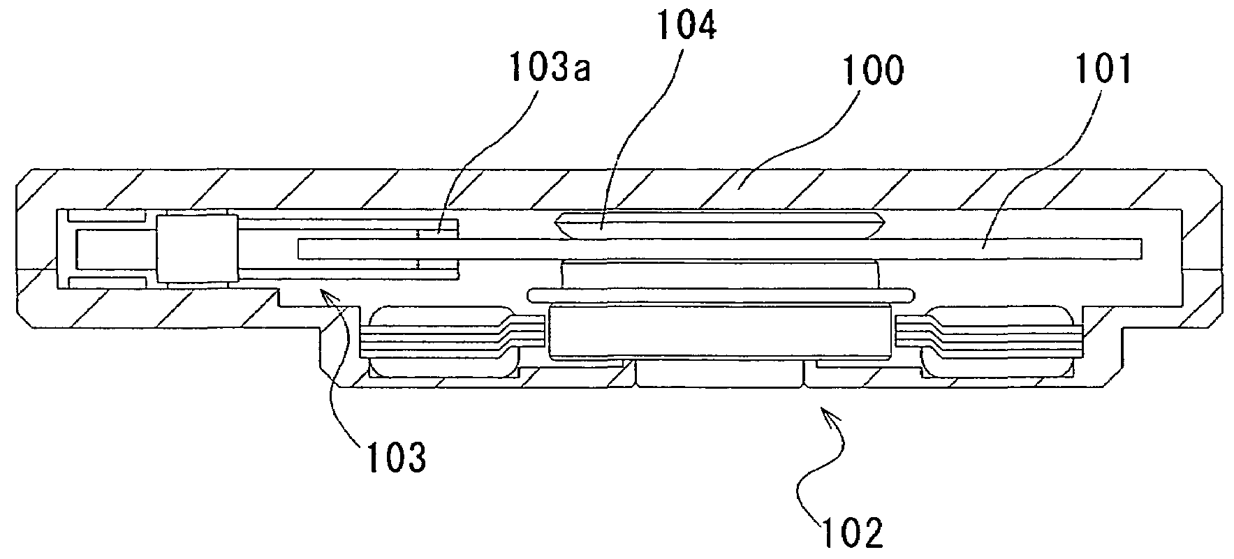
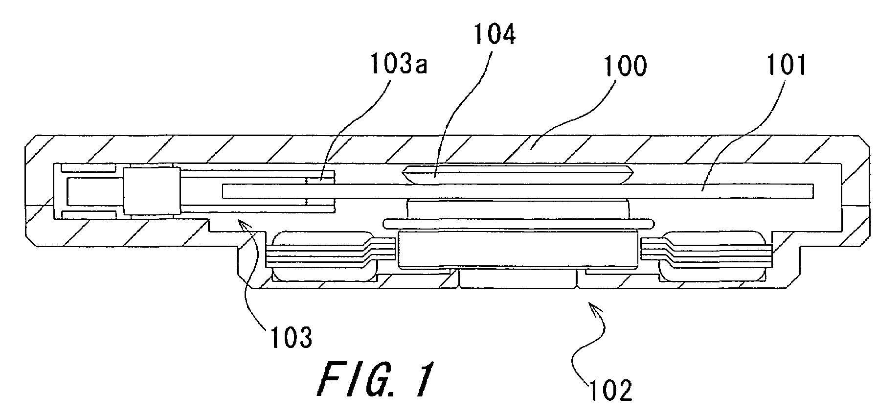
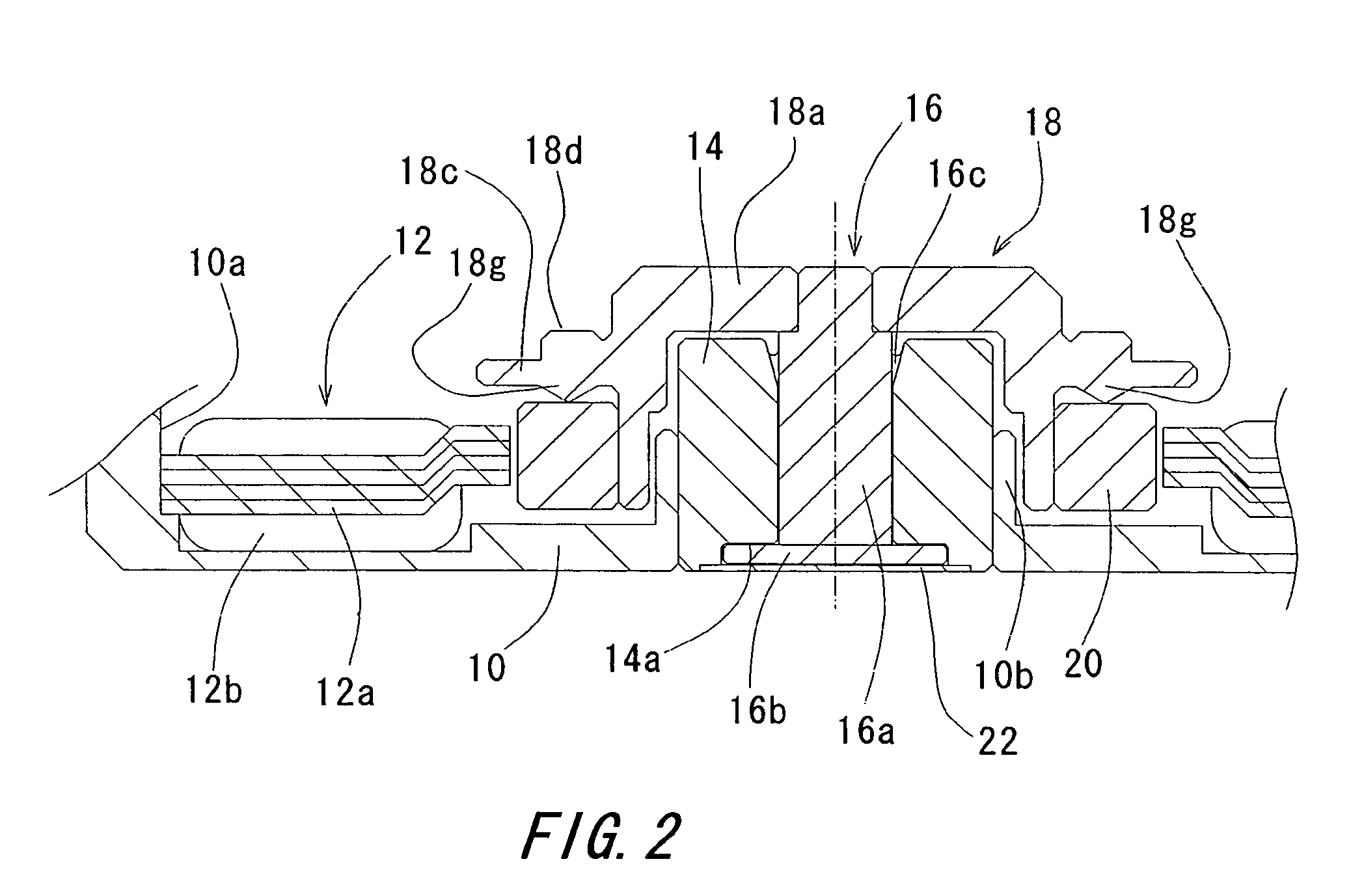
[0029]FIGS. 1 to 3 illustrate the first preferred embodiment of the present invention. FIG. 1 is a cross sectional view of a hard disk drive device in which a spindle motor according to one preferred embodiment of the present invention is installed. FIG. 2 is a schematic cross sectional view of a substantial part of the motor according to the first preferred embodiment of the present invention. FIG. 3 is a plain view of the rotor magnet according to the first preferred embodiment of the present invention.

[0030]Referring now to FIG. 1, the hard disk drive device includes: a motor 102; a hard disk 101, e.g., a magnetic disk, fixed to the motor 102; a magnetic head 103a which reads and writes data; an actuator 103 which allows the magnetic head 103a to move in the radial direction; and a case 100 which encloses the above components. The magnetic head 103a is installed on both the upper and...


PUM


Abstract

A spindle motor includes a rotor magnet including a plurality of pairs of magnetic poles polarized in a radial direction and arranged along a circumferential direction of the rotor magnet and a rotor hub supporting the rotor magnet and being rotatable around an axis of the circular shape of the rotor magnet. A circular surface in the form of a convex portion is provided on a magnetic shield portion of the rotor hub and is arranged to oppose one axial end surface of the rotor magnet and abut against the rotor magnet such that a gap is provided between the axial end surface of the rotor magnet and the circular surface of rotor hub.

Description

BACKGROUND OF THE INVENTION[0001]1. Field of the Invention[0002]The present invention generally relates to a spindle motor and more particularly relates to a spindle motor for rotating a disk-shaped storage medium, such as magnetic disks, typified by hard disks; various types of optical disks; and magnetic optical disks.[0003]2. Description of the Related Art[0004]Recently, hard disk drive devices are being installed in mobile devices. These mobile devices are battery-powered, and in order to ensure longer battery operating time, the spindle motors (hereinafter referred to as motors) used in the hard disk drive devices are required to have severely low power consumption.[0005]FIGS. 10 and 11 are sectional views of conventional motors. In the conventional motors shown in FIG. 10 and 11, the circular rotor magnet 2 is fixed to a lower side and in a radially-outward portion of the rotor hub 1. In addition, the rotor magnet 2 opposes the stator 3 with a gap maintained between the rotor ...

Claims


Application Information

Patent Timeline
Patent Type & Authority Patents(United States)
IPC IPC(8): H02K21/12
CPCH02K1/2733H02K1/28
Inventor IGUCHI, TAKURO
Owner NIDEC CORP
Why Eureka
Try Eureka