Controller and method for collision detection

a technology of collision detection and controller, which is applied in the direction of digital transmission, data switching network, instruments, etc., can solve problems such as data collision and data loss

Active Publication Date: 2016-07-05
SONY CORP
View PDF16 Cites 0 Cited by
  • Summary
  • Abstract
  • Description
  • Claims
  • Application Information

AI Technical Summary

Problems solved by technology

This may lead to data collision and thereby to data loss.

Method used


Image

  • Controller and method for collision detection
  • Controller and method for collision detection
  • Controller and method for collision detection

Examples


Embodiment Construction

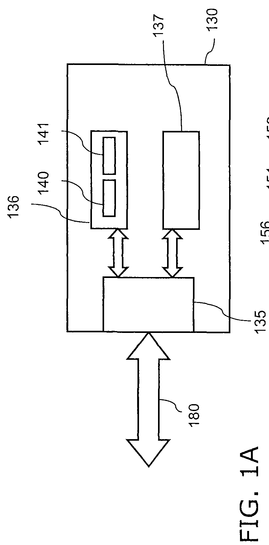
[0032]Referring now to the drawings, wherein like reference numerals designate identical or corresponding parts throughout the several views, FIG. 1A illustrates an embodiment of a controller 130. The controller 130 includes a controller interface 135 that is connected to a bus 180 outside of the controller 130, which is connected to a system such as a satellite receiver system. The controller 130 further includes a sensor 136 with a voltage source 140 and a current sensor 141, which is connected to the controller interface 135. The voltage source 140 is configured to apply a sensing voltage to the bus 180 and the current sensor 141 is configured to measure a sensing current on the bus 180. The controller 130 further includes a transmitter 137 connected to the controller interface 135 adapted to transmit data on the bus 180.

[0033]As long as no data signal is transmitted to the bus 180 by the transmitter 137, a supply voltage is applied to the bus 180 by the controller 130. The suppl...


PUM


Abstract

A method for detecting a signal activity on a bus comprises measuring a current on the bus, and determining a signal activity based on the measured current.

Description

BACKGROUND[0001]1. Field of the Disclosure[0002]The present disclosure relates to a controller and a method for detecting a signal activity on a bus.[0003]2. Description of Related Art[0004]In systems where several individual masters can be connected to one slave, as e.g. single cable satellite antenna systems, more than one master can start to transmit data to the slave at the same time. This may lead to data collision and thereby to data loss. To guarantee a satisfactory operation of all transmitting units it is necessary to provide means to detect and avoid data collision.[0005]In single cable satellite antenna systems, several receivers are connected to a single cable interface (SCIF). Usually up to 8 individual receivers can be connected to the SCIF. Each of them can be tuned to a different frequency. A common standard is to use the “Digital Satellite Equipment Control Bus” (DiSEqC) for the communication between the receivers and the SCIF.[0006]According to the Single Cable sta...

Claims


Application Information

Patent Timeline
Patent Type & Authority Patents(United States)
IPC IPC(8): G01R27/32H04L12/413G01R27/28G06F1/00
CPCG01R27/28H04L12/413G06F1/00G06F2101/00G06F2200/00H04Q2213/13299
Inventor EITEL, BENGUTH, HEIMO
Owner SONY CORP
Why Eureka
Try Eureka