Closing tool

a tool and tool body technology, applied in the field of closing tools, can solve the problems of small differences in closure size and limited load margin of o-rings, and achieve the effect of simple construction and convenient operation

Active Publication Date: 2016-07-12
KRONES AG
View PDF34 Cites 5 Cited by
  • Summary
  • Abstract
  • Description
  • Claims
  • Application Information

AI Technical Summary

Benefits of technology

[0004]Thus, the disclosure has as one aspect to render a closing tool for a closing machine for placing a closure on a container universally usable.
[0005]The magnetic actuator employed in accordance with the disclosure strongly increases the tolerance range to be coped with by the gripping device, namely in view of dimensions / tolerances and in view of contour or in view of mechanical strength.
[0009]In one embodiment the gripping members are arranged circularly about a center line and are mounted pivotably about a pivot axis, and one magnet of the magnetic actuator is disposed on the gripping member, while the second magnet of the gripping device is fixed to a holder which is movable along the center line in such a way that the gripping device is opened or closed by magnetic attraction and magnetic repulsion. This embodiment has the additional advantage that the closing tool can thus be easily equipped for an aseptic operation, wherein merely the holder is received in a sealed sleeve (pervious to the magnetic field) so that a contamination of the aseptically held closing tool from the drive side (screwing and stroke movements) is prevented.
[0010]A particularly simple construction is obtained if the gripping members are arranged in a holder to be radially displaceable and the magnets of the magnetic actuator are arranged around the gripping segments distributed to two concentric circles.

Problems solved by technology

The load margin of an O-ring is limited, however, so that only small differences in the closure sizes can be covered.

Method used


Image

  • Closing tool
  • Closing tool
  • Closing tool

Examples


Embodiment Construction

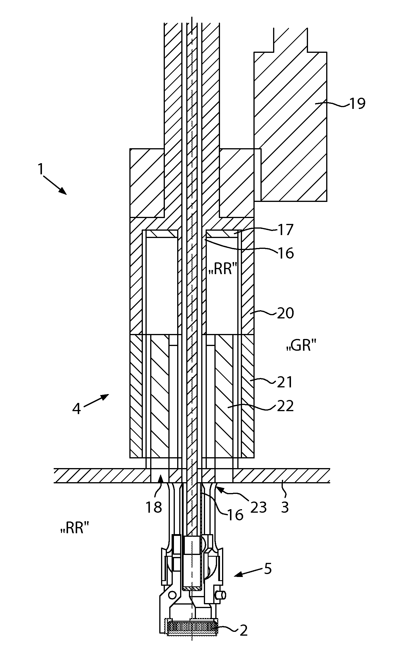
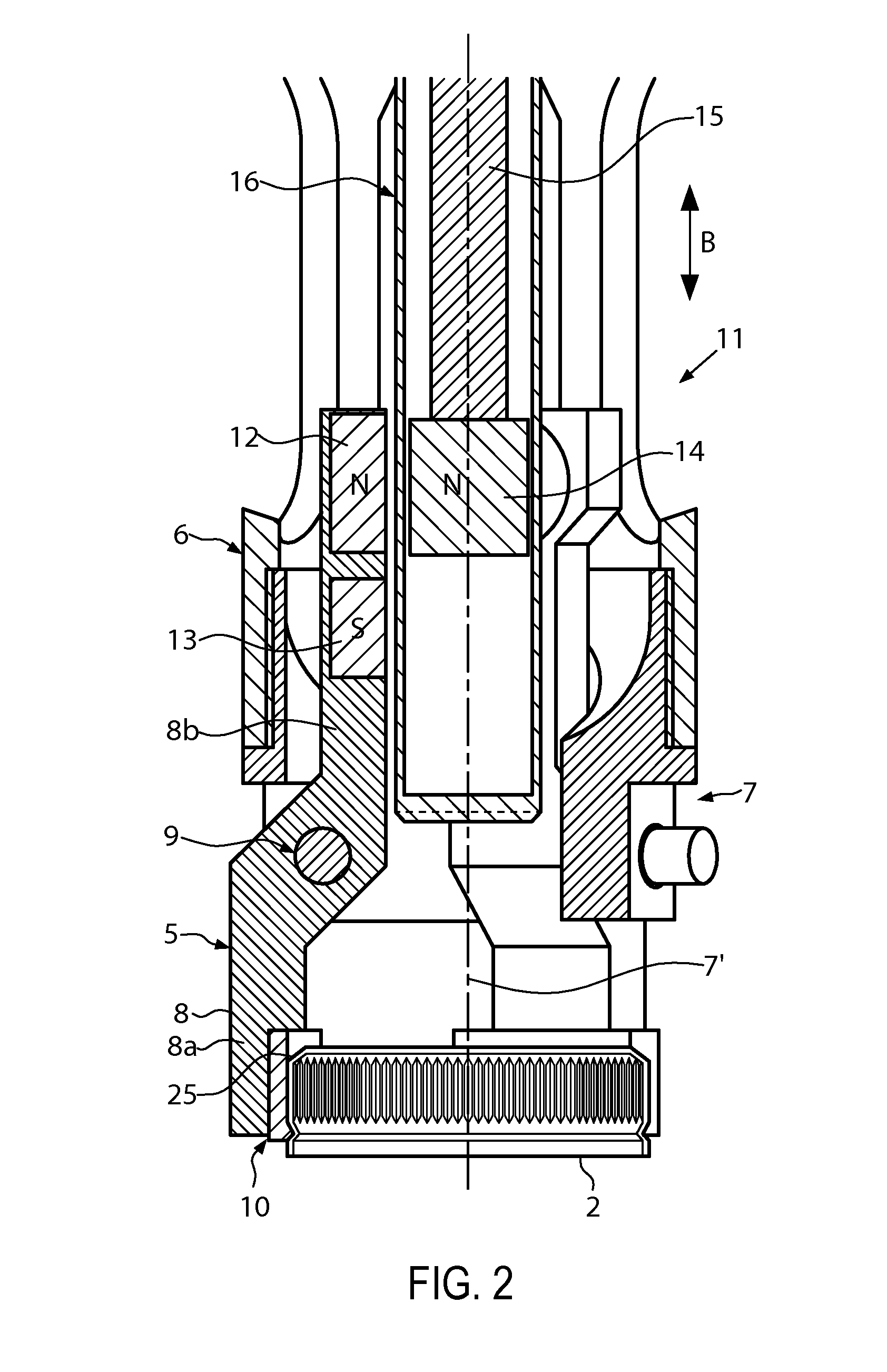
[0021]FIG. 1 shows in a schematic view and in a longitudinal section a closing unit 1 of a closing machine for closing non-illustrated containers with a closure 2. The closing unit 1 according to the illustrated embodiment is designed for aseptic operation, and comprises a partition wall 3 of the closing machine which separates a clean room area RR from a gray room GR. The partition wall 3 divides the closing unit 1 into a drive part 4 and a closing tool 5.

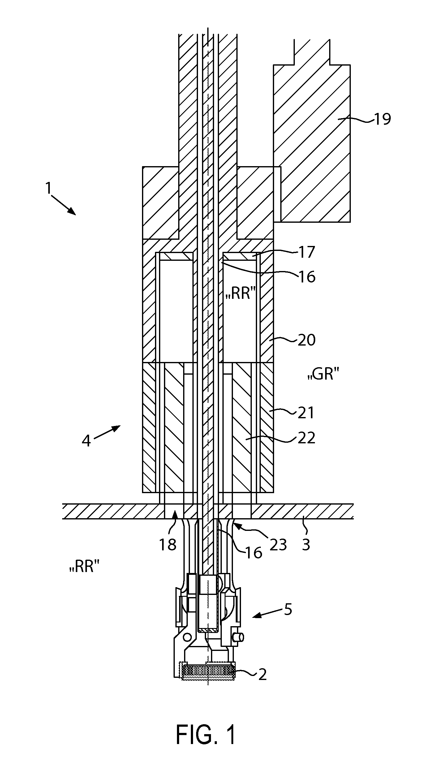
[0022]As can also be seen in conjunction with FIG. 2, the tool 5 comprises a case 6 in which a gripping device 7 is accommodated. Preferably, the gripping device 7 is accommodated in the case 6 to be exchangeable and can be exchanged for the purpose of handling different closures. In particular, if the design is for an aseptic operation, these components are mounted free from gaps and in a sealed manner.

[0023]In the embodiment as illustrated, the gripping device 7 comprises a plurality of gripping members 8 in the form of gripping...


PUM


Abstract

A closing tool for a closing machine for placing a closure on a container, where a holding force is applied to the closure by means of a gripping device. In order to obtain a universal embodiment for the closing tool the gripping device is provided with a magnetic actuator, such as with permanent magnets, for applying the holding force.

Description

CROSS-REFERENCE TO RELATED APPLICATION[0001]The present application claims the benefit of priority of German Application No. 102011005306.9 , filed Mar. 9, 2011 . The entire text of the priority application is incorporated herein by reference in its entirety.FIELD OF THE DISCLOSURE[0002]The disclosure relates to a closing tool of the type used in beverage bottling operations.BACKGROUND[0003]A closing tool of this type is known from WO 2004 / 009484 . The known closing tool comprises a gripping device formed of a plurality of gripping segments which are grouped around a center line in a circular fashion. In use, the center line coincides with the center line of the container. The gripping segments are capable of approaching and moving away from the center line to a limited extent. This embodiment is to compensate for small tolerances which may appear on a regular basis, even if the production of the closures is carried out with utmost care, so as to reduce the error rate of closures th...

Claims


Application Information

Patent Timeline
Patent Type & Authority Patents(United States)
IPC IPC(8): B65B7/28B67B3/20
CPCB67B3/2066Y10S7/901Y10T279/23B67B2201/08B67B3/268
Inventor SCHOENFELDER, MARKUS
Owner KRONES AG
Why Eureka
Try Eureka