
Electrostatic spray tool system

a technology of electrostatic spraying and spraying tools, applied in the direction of electrostatic spraying apparatus, spraying power supply, induction-charge spraying, etc., can solve the problems of blocking or inhibiting spraying operations in tight spaces, charging on electrically charged materials

Active Publication Date: 2016-07-26
CARLISLE FLUID TECH INC
View PDF14 Cites 1 Cited by
  • Summary
  • Abstract
  • Description
  • Claims
  • Application Information

AI Technical Summary

Problems solved by technology

Unfortunately, the electric charge on the electrically charged material may block or inhibit spraying operations in tight spaces (e.g., corners).

Method used


Image

  • Electrostatic spray tool system
  • Electrostatic spray tool system
  • Electrostatic spray tool system

Examples


Embodiment Construction

[0019]One or more specific embodiments of the present invention will be described below. In an effort to provide a concise description of these embodiments, all features of an actual implementation may not be described in the specification. It should be appreciated that in the development of any such actual implementation, as in any engineering or design project, numerous implementation-specific decisions must be made to achieve the developers' specific goals, such as compliance with system-related and business-related constraints, which may vary from one implementation to another. Moreover, it should be appreciated that such a development effort might be complex and time consuming, but would nevertheless be a routine undertaking of design, fabrication, and manufacture for those of ordinary skill having the benefit of this disclosure.

[0020]When introducing elements of various embodiments of the present invention, the articles “a,”“an,”“the,” and “said” are intended to mean that ther...


PUM


Abstract

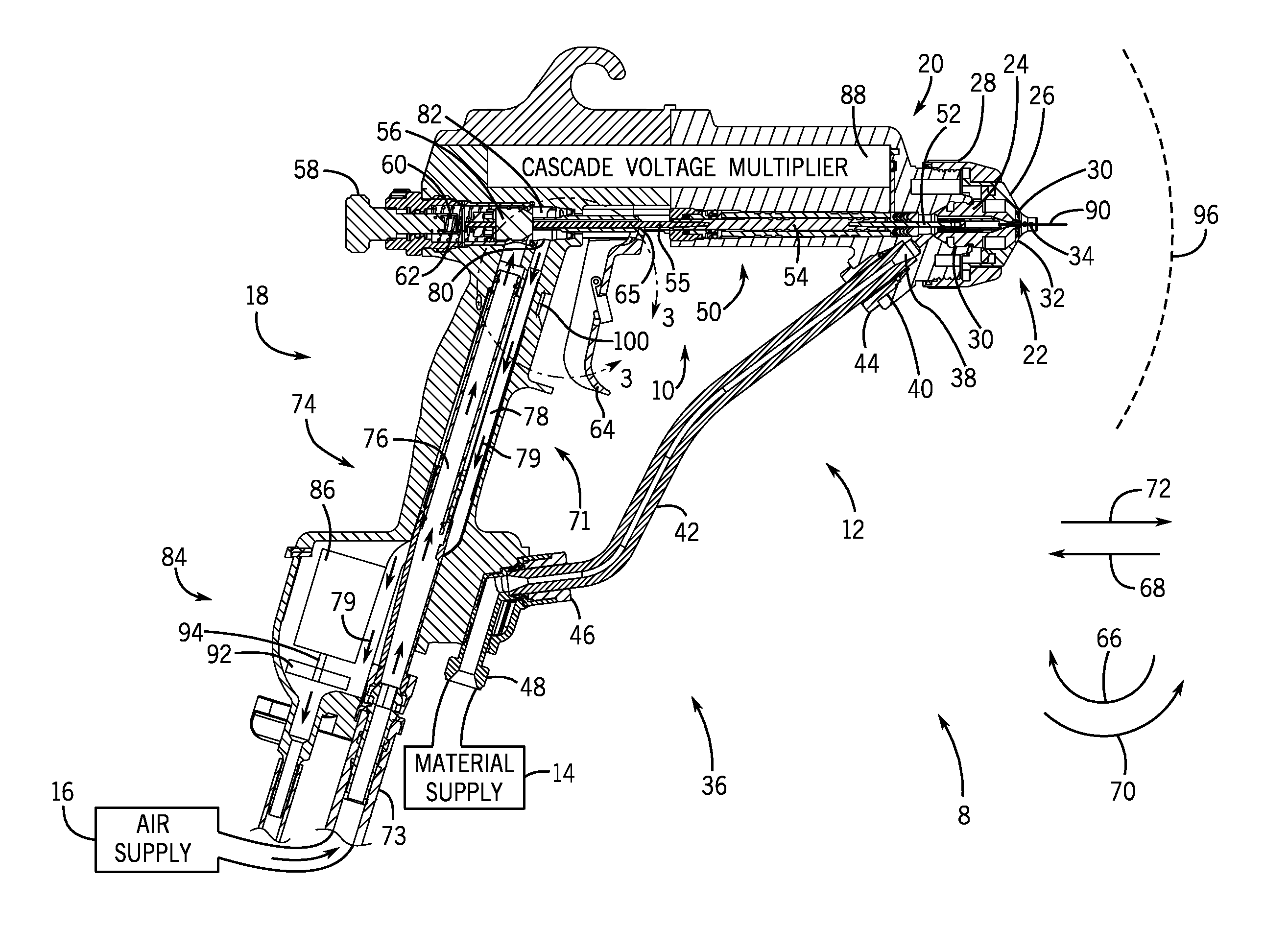
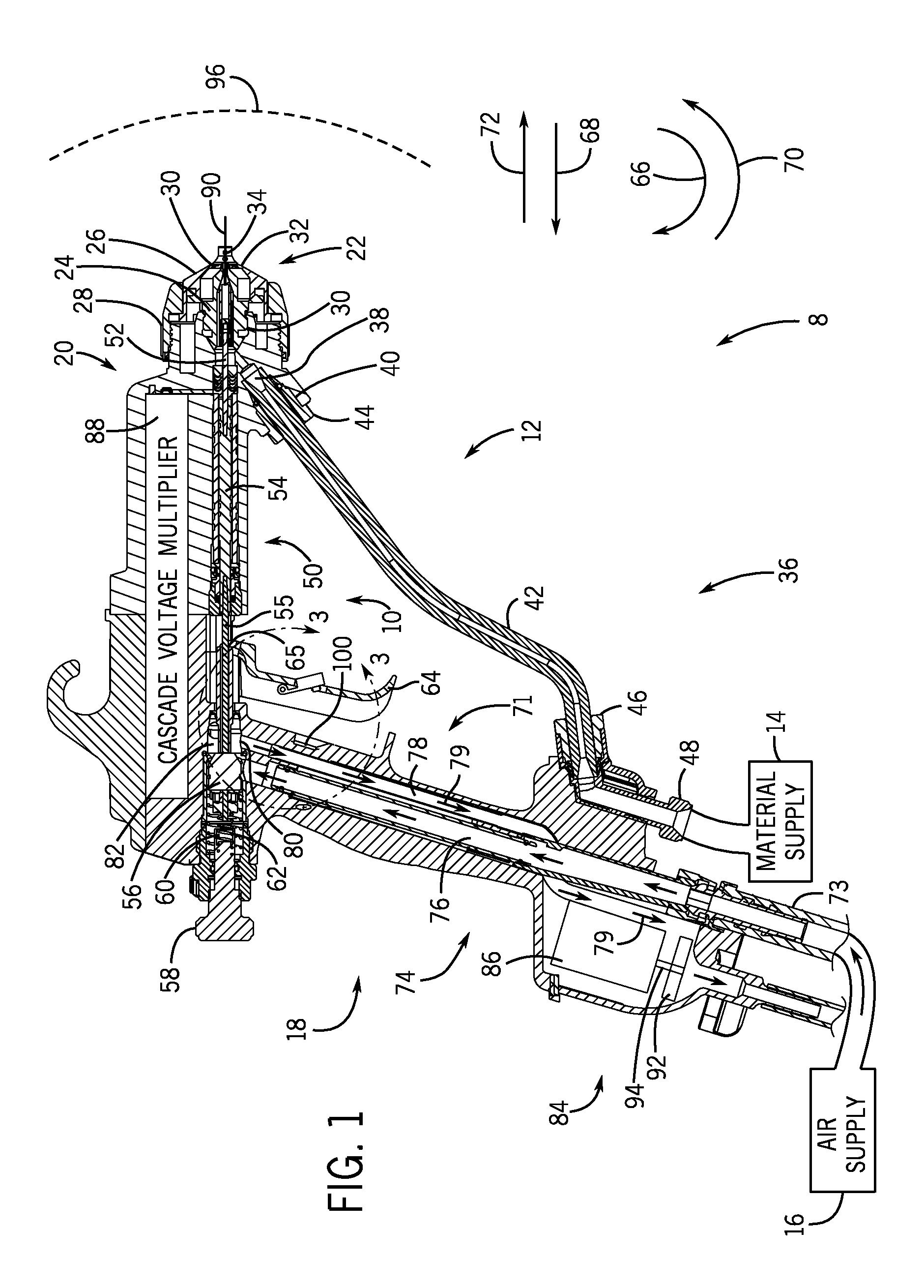
A system including an electrostatic tool including a handle, a first trigger configured to move between a first trigger position and a second trigger position, wherein the electrostatic tool is configured to be inactive when the first trigger is in the first trigger position and to spray a coating material when the first trigger is in the second trigger position, an electrostatic activation system configured to activate and deactivate electrical charging of the coating material, and wherein the first trigger and the electrostatics activation system may be separately and simultaneously engaged with a single hand.

Description

CROSS-REFERENCE TO RELATED APPLICATION[0001]This Application is a Non-Provisional Application and claims priority to U.S. Provisional Patent Application No. 61 / 813,135, entitled “Electrostatic Spray Tool System”, filed Apr. 17, 2013, which is herein incorporated by reference.BACKGROUND[0002]The invention relates generally to an electrostatic spray tool.[0003]Electrostatic spray tools output sprays of electrically charged materials to more efficiently coat objects. For example, electrostatic tools may be used to paint objects. In operation, a grounded target attracts electrically charged materials sprayed with compressed air from an electrostatic tool. As the electrically charged material contacts the grounded target, the material loses the electrical charge. Unfortunately, the electric charge on the electrically charged material may block or inhibit spraying operations in tight spaces (e.g., corners).BRIEF DESCRIPTION[0004]Certain embodiments commensurate in scope with the originall...

Claims


Application Information

Patent Timeline
Patent Type & Authority Patents(United States)
IPC IPC(8): B05B5/00B05B5/053B05B5/043B05B9/01B05B5/025B05B1/00B05B5/03B05B12/00
CPCB05B5/03B05B1/005B05B5/0255B05B5/043B05B5/053B05B5/0533B05B9/01B05B12/002B05B5/0532
Inventor HASSELSCHWERT, DANIEL J.
Owner CARLISLE FLUID TECH INC
Learn More