
Aerodynamic wingsail

a technology of aerodynamic wings and wings, applied in the field of sailing vessels, can solve the problems of compromising simplicity and safety, only increasing speed of cup catamarans, etc., and achieve the effect of superior aerodynamic efficiency of wingsails

Active Publication Date: 2016-07-26
SALZ DAVID B
View PDF22 Cites 0 Cited by
  • Summary
  • Abstract
  • Description
  • Claims
  • Application Information

AI Technical Summary

Benefits of technology

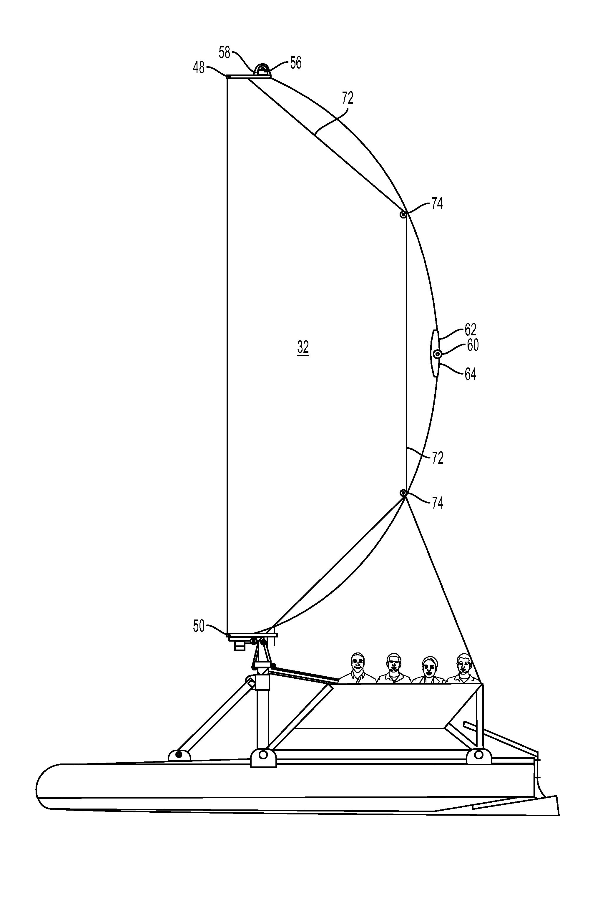
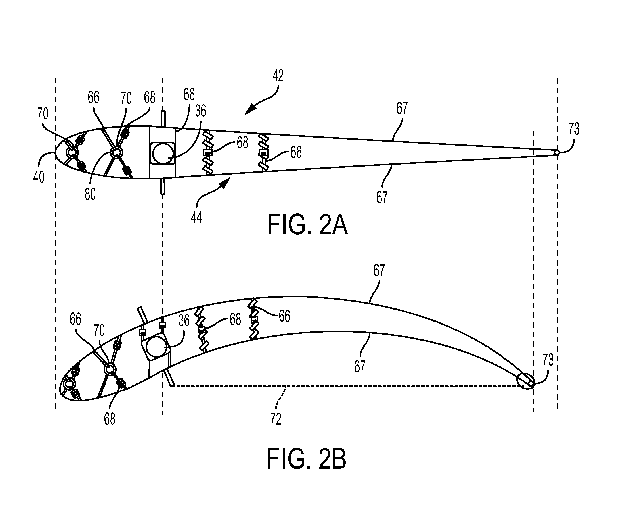
[0015]Furthering previous wingsail concepts, the invention presented herein combines the superior aerodynamic efficiency of wingsails with safety and simplicity rivaling conventional sails, thereby creating a useful advance in sailboat evolution. The present inventions relate to aerodynamic wingsails comprising lightweight sail cloths that have integral internal tubular slots which contain flat batten strips which are resilient and made of carbon fiber or other spring like material such as plastic / metal composites, fiberglass or the like. To form dual surfaces for the “wing” sail, the surface is folded in half about its centerline creating the wing profile around the mast. Related novel hardware and components control the deployment and operation of the wingsail and vessel, as the engineering designs also include top and bottom bracket assemblies, camber control components, hinged arms, bearings, floatation blocks, and certain free standing mast applications (having no stays). A unique fundamental wingsail is also disclosed having minimal components and simplicity of operation.

Problems solved by technology

For example, the recently developed rigid wingsails used on the America's Cup catamarans have only increased speed, while compromising simplicity and safety.
However, none of the above-referenced patents or the prior art address the designs, components and / or operation of the instant aerodynamic wingsail, which constitutes a substantial improvement over the art.

Method used


Image

  • Aerodynamic wingsail
  • Aerodynamic wingsail
  • Aerodynamic wingsail

Examples


Embodiment Construction

Fundamental Wingsail

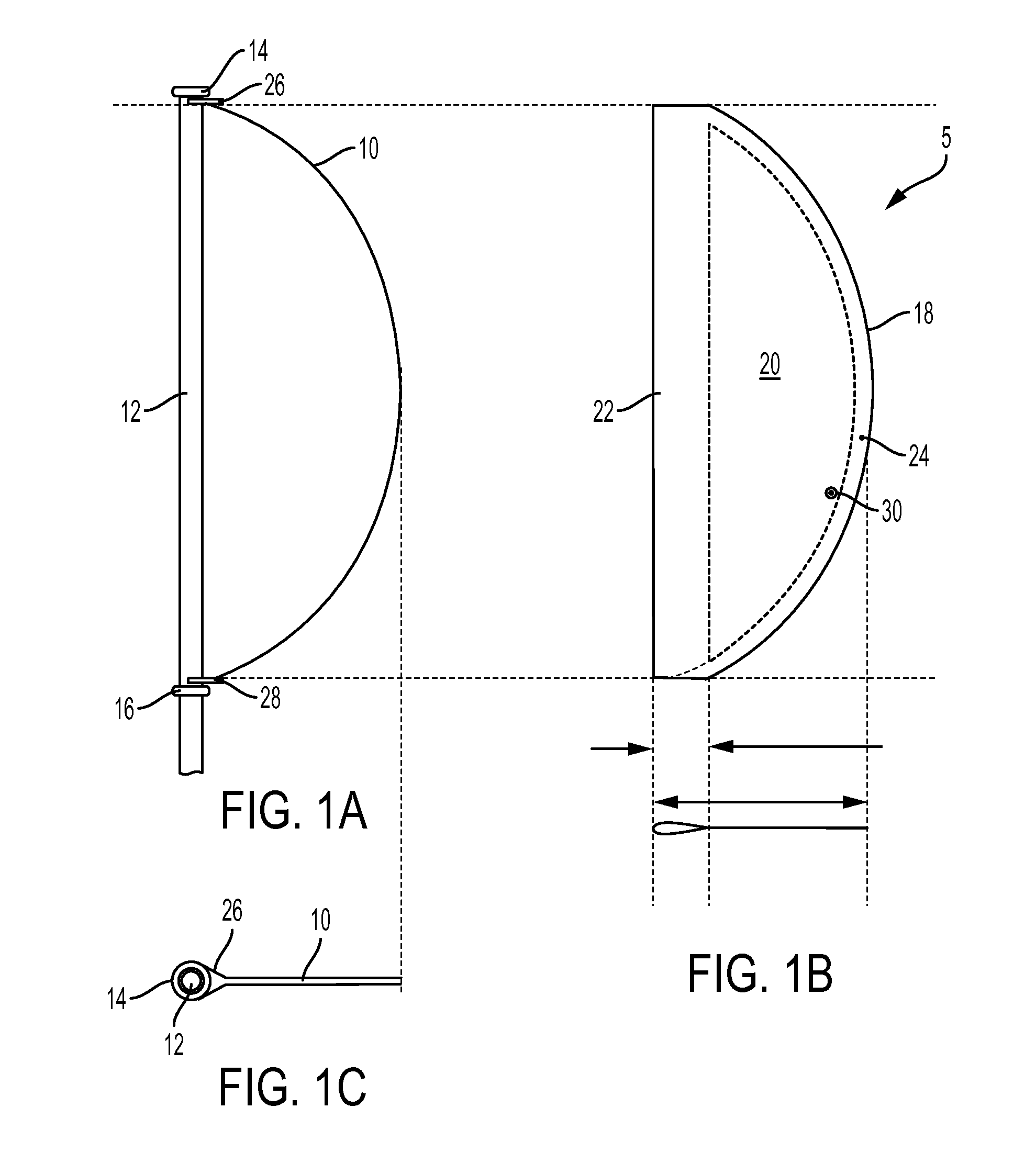
[0037]The fundamental design of an inventive wingsail 5 of the instant invention is shown in FIGS. 1A and 1B. This novel design utilizes a tensioned bow rod 10, a structural component of simplicity yet effectiveness, to replace previous methods of supporting and tensioning sails. The entire device consists of a curved or tubular mast 12 with two flanges 14 and 16, a cloth sail 18, bow 10 and a singular control rope. The semi-circular sailcloth surface 20 has internal sleeves 22 and 24 for the mast 12 and bow rod 10. The bow is a tensile rod with U-shaped brackets 26 and 28 on each end. The preferred rod materials are fiberglass and carbon fiber, but bamboo and hardwoods are viable alternatives. The wingsail surface 20 is tensioned between the bow rod 10 and mast 12 when the U-shaped brackets 26 and 28 are captured on the mast between the two flanges, one above and the other below the wingsail 5. The flange beneath the wingsail may be fixed to the mast or it can b...


PUM


Abstract

An aerodynamic wingsail and mast assembly, which does not utilize a boom or gaff, and which is simply designed to include a singular sailcloth and resilient bow rod which are removably attached to a free standing mast. The bow rod includes a pair of open-ended brackets to engage the mast, and is positioned in a curved sleeve on the trailing edge of the sailcloth. The sailcloth includes a forward sleeve for receiving the mast. Flanges on the mast engage the brackets, and the sailcloth is simply slid off the mast by releasing the brackets and tension of the bow rod. Alternative embodiments are described for 3 dimensional wingsails.

Description

CROSS REFERENCE TO RELATED APPLICATIONS[0001]This application claims priority from the Provisional Application, Ser. No. 61 / 971,791, filed on Mar. 28, 2014.STATEMENT REGARDING FEDERALLY SPONSORED RESEARCH OR DEVELOPMENT[0002]N / ABACKGROUND OF THE INVENTION[0003]1. Field of the Invention[0004]The present invention relates generally to sailing vessels, and more particularly to unique designs for aerodynamic wingsails having lightweight sail clothes, support members, mast features, hardware assemblies, as well as operation and control components.[0005]2. Description of the Prior Art[0006]Since their invention over thousands of years ago, sailboats have evolved in a multitude of fascinating ways. Many of the design advances made during that time were practical in nature, such as improving safety and simplifying operation, while others were made specifically to increase boat speed. For example, the recently developed rigid wingsails used on the America's Cup catamarans have only increased...

Claims


Application Information

Patent Timeline
Patent Type & Authority Patents(United States)
IPC IPC(8): B63H9/04B63H9/06
CPCB63H9/0607B63H9/1021B63H9/061
Inventor SALZ, DAVID B.
Owner SALZ DAVID B
Learn More