Diaphragm disk

a diaphragm and disk technology, applied in the direction of valve operating means/releasing devices, mechanical equipment, transportation and packaging, etc., can solve the problems of increasing the weight of the disk and the manufacturing cost, and achieve the effect of accurately and stably centered on the diaphragm, light and less expensiv

Active Publication Date: 2016-07-26
ZURN INDS
View PDF54 Cites 0 Cited by
  • Summary
  • Abstract
  • Description
  • Claims
  • Application Information

AI Technical Summary

Benefits of technology

[0011]The improved diaphragm disk of the present invention is made out of composite material having a rubber layer over a portion of the disk making it lighter and less expensive than the prior art rubber-coated brass disks. The diaphragm disk of the present invention also includes a plurality of short and rounded extensions circumferentially spaced around the disk making it more accurately and stably centered on the diaphragm.

Problems solved by technology

The use of brass for the diaphragm disk increases the weight of the disk as well as the manufacturing costs.

Method used


Image

  • Diaphragm disk
  • Diaphragm disk
  • Diaphragm disk

Examples


Embodiment Construction

[0021]For purposes of the description hereinafter, spatial orientation terms, if used, shall relate to the referenced embodiment as it is oriented in the accompanying drawing figures or otherwise described in the following detailed description. However, it is to be understood that the embodiment described hereinafter may assume many alternative variations and embodiments. It is also to be understood that the specific devices illustrated in the accompanying drawing figures and described herein are simply exemplary and should not be considered as limiting.

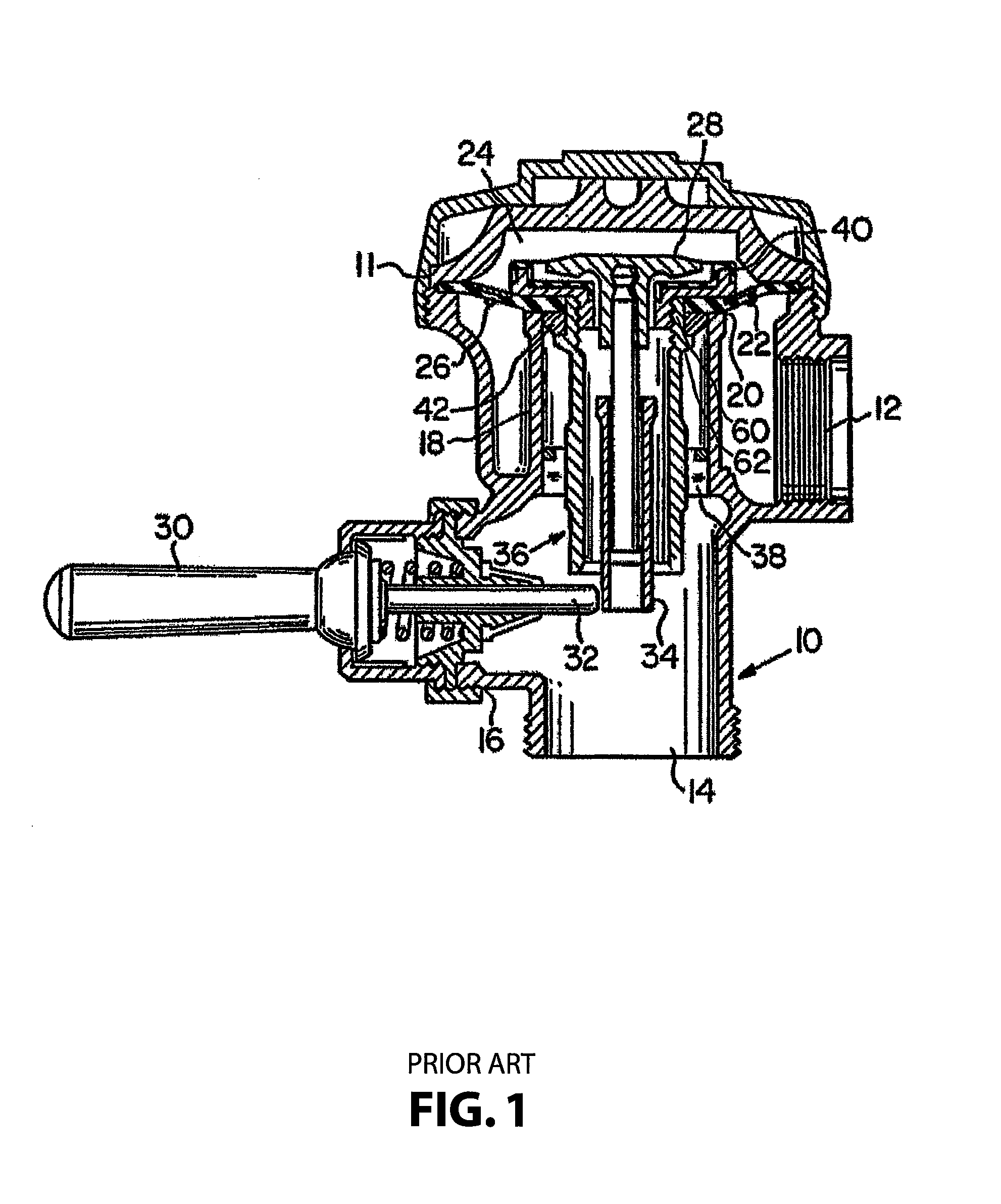
[0022]FIG. 1 illustrates a typical diaphragm flush valve assembly for use in water closets and urinals. As shown in FIG. 1, a typical diaphragm flush valve assembly has a hollow body 10 and includes an inlet connection 12, an outlet connection 14, and a handle connection 16. Barrel18 is positioned within the flush valve such that the connection between inlet 12 and outlet 14 is through barrel 18. An annular main valve seat 20 is form...


PUM


Abstract

A diaphragm type flush valve for use with toilet devices such as urinals and water closets that includes a valve member, a diaphragm, a guide member extends downwardly from the diaphragm, and a disk positioned on top of the diaphragm. The disk is threadably attached to the guide member and functions to secure the diaphragm, the disk, and the guide member into the valve member. The disk includes a rigid body made of a composite material and a seal member made of an adhesive and a thin layer of rubber, with the seal member having a portion on an upper surface of the disk for sealing contact with a relief valve. The disk also includes a plurality of spaced protrusions and inwardly directed on its upper surface in order to add accuracy and stability to the diaphragm assembly.

Description

CROSS REFERENCE TO RELATED APPLICATIONS[0001]This application claims the benefit of U.S. Provisional Patent Application No. 61 / 757,988, filed Jan. 29, 2013, entitled “Diaphragm Disk”, which is hereby incorporated by reference in its entirety.BACKGROUND OF THE INVENTION[0002]1. Field of the Invention[0003]The present invention relates to diaphragm flush valves for use in water closets and urinals and, more particularly, to a diaphragm disk for use in a diaphragm flush valve.[0004]In particular the invention relates to improving the accuracy and stability of the flush valve. The diaphragm disk of the present invention is made out of composite material having a rubber layer over a portion of the disk making it less expensive than the prior art rubber-coated brass disks. The diaphragm disk of the present invention also includes a plurality of short and rounded extensions circumferentially spaced around the disk making it more accurately and stably centered on the diaphragm.[0005]2. Desc...

Claims


Application Information

Patent Timeline
Patent Type & Authority Patents(United States)
IPC IPC(8): E03D3/00F16K31/385E03D3/06
CPCE03D3/00E03D3/06F16K31/3855Y10T137/0491
Inventor FUNARI, MICHAEL A.ELTING, LARRY M.MARKIJOHN, JEROME S.
Owner ZURN INDS
Why Eureka
Try Eureka