Support for a crane

a technology for supporting a crane and a crane body, which is applied in the direction of braking devices for hoisting equipment, base supporting structures, load-engaging elements, etc., can solve the problems of crane loss of stability, overall load bearing capacity, and inability to simultaneously support all the tilt edges of the crane, and achieves the effect of light and as inexpensiv

Active Publication Date: 2020-09-22
LIEBHERR WERK EHINGEN
View PDF9 Cites 0 Cited by
  • Summary
  • Abstract
  • Description
  • Claims
  • Application Information

AI Technical Summary

Benefits of technology

[0011]On the utilization of a pair of first support beams that can be deployed less far than a pair of second support beams, the first support beams can be dimensioned as correspondingly smaller and thus lighter and less expensive. At the same time, it is made possible by the arrangement of the support beams in accordance with the present disclosure to ensure a spacing that is as large as possible between the center of rotation of the superstructure or the center of mass of a corresponding crane and the lateral tilt edges. Only a minimal loss of the relevant support width defined by the lateral tilt edges and thus of the stability toward the lateral tilt edge is thus achieved with respect to the supports known from the prior art and to the parallelogram-shaped support bases occurring therein.
[0014]It is advantageous in a further preferred embodiment that the first support beams are arranged in a plane transverse to the longitudinal direction of the support or offset from one another. A further preferred embodiment can be configured such that the second support beams are arranged in a plane transverse to the longitudinal direction of the support or offset from one another. The planes in which the support beams can be arranged can in this respect be arranged perpendicular to the longitudinal direction of the support. The indications can furthermore relate to a state in which the support beams are extended to stabilize the crane and are in particular aligned perpendicular to the longitudinal direction of the support. With support beams arranged offset from one another, said support beams can in particular be offset from one another in the longitudinal direction of the support. They can here be offset by an amount or by a length that corresponds to their width or extent in the longitudinal direction. It is thus possible to arrange the support beams correspondingly arranged offset from one another in a manner correspondingly offset from one another in the further structure of the support and, for example, to utilize the total width or a large part of the width of the support for receiving or for providing the support beams. The offset arrangement of the support beams can furthermore relate to the arrangement of the coupling regions of the support beams by means of which the support beams are connected or coupled to the further structure of the support.
[0015]It is possible in a further preferred embodiment that the second support beams are arranged in a rear or front region of the support. The first support beams can here be correspondingly arranged in the respective other region of the support. The center of rotation of a superstructure that can be provided at the vehicle frame or the center of mass of the corresponding crane can furthermore be arranged in the rear region or in the front region of the support. A case is thus also described in which the center of rotation of a superstructure is located closer to the second support beams than to the first support beams. The center of rotation can thus be arranged closer to either the first support beams or to the second support beams.

Problems solved by technology

This procedure depends on a plurality of constraints and is not simultaneously possible for all the tilt edges of the crane.
If the spacing of the slewing platform contact point from one of the tilt edges is reduced here, the crane loses stability, and thus load bearing capacity overall, in the direction of the reduced spacing from the tilt edge.

Method used


Image

  • Support for a crane

Examples


Embodiment Construction

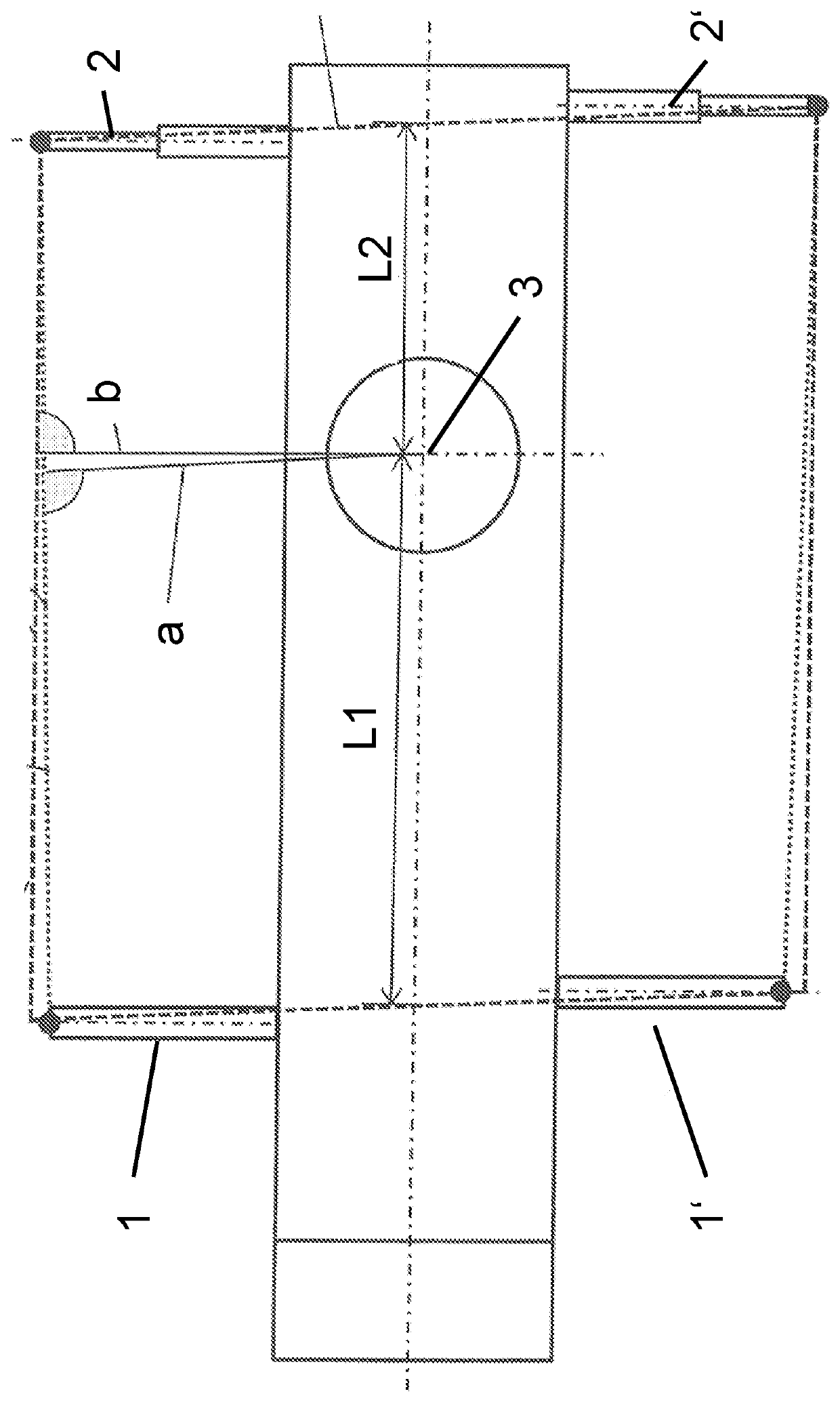
[0020]The two first mutually oppositely disposed support beams 1, 1′ here have a smaller maximum deployment range than the two second mutually oppositely disposed support beams 2, 2′. The maximum deployment range can here be defined as the maximum horizontal extent of the support beams 1, 1′, 2, 2′ perpendicular to the longitudinal axis of the support and away from the support. This extent is at a maximum when the support beams 1, 1′, 2, 2′ have been telescoped or pivoted outwardly. The longitudinal axis of the support is recognizable as the longest, transversely extending chain-dotted line.

[0021]The dashed and dotted lines show the extent of a parallelogram-shaped support base from the prior art (dashed) and of a trapezoidal or at least approximately trapezoidal support base in accordance with the present disclosure (dotted).

[0022]Lateral tilt edges of the support bases are shown at the top and bottom in FIG. 1 and front or rear tilt edges of the support bases that are associated w...


PUM


Abstract

The present disclosure relates to a support for a crane, in particular for a mobile crane, having at least two first support beams and two second support beams that are each arranged pairwise at mutually oppositely disposed sides of the support.

Description

CROSS REFERENCE TO RELATED APPLICATION[0001]This application claims priority to German Patent Application No. 10 2017 001 128.1, entitled “Support for a Crane,” filed Feb. 7, 2017, the entire contents of which is hereby incorporated by reference in its entirety for all purposes.TECHNICAL FIELD[0002]The present disclosure relates to a support for a crane, in particular for a mobile crane, having at least two first support beams and two second support beams that are each arranged pairwise at mutually oppositely disposed sides of the vehicle frame.BACKGROUND AND SUMMARY[0003]When configuring cranes or supports for cranes, an optimized ratio of tilt edges to one another inter alia plays an exceptional role. The spacing of the contact point of a slewing platform on an undercarriage of a corresponding crane from the individual tilt edges of the crane in a working position and in this respect from correspondingly extended or supported support beams is inter alia fixed in this process. The ...

Claims


Application Information

Patent Timeline
Patent Type & Authority Patents(United States)
IPC IPC(8): B66C23/78B66C23/84B66C23/88
CPCB66C23/84B66C23/78B66C23/88B66C5/00
Inventor HENKEL, JOACHIMSCHILKE, HOLGER
Owner LIEBHERR WERK EHINGEN
Why Eureka
Try Eureka