
Holographic storage system with improved beam overlap

a technology of beam overlap and storage system, applied in the field of apparatus and methods, can solve the problem of limiting the maximum useful thickness of holographic material, and achieve the effect of light and less expensiv

Inactive Publication Date: 2010-04-22
THOMSON LICENSING SA
View PDF7 Cites 1 Cited by
  • Summary
  • Abstract
  • Description
  • Claims
  • Application Information

AI Technical Summary

Benefits of technology

[0014]It has been found that it is not necessary to place the foci of the one or more reference beams into the Fourier plane of the object beam. If the Fourier plane and the focal plane of the one or more reference beams are shifted along the optical axis relative to each other, the overlap of the one or more reference beams and the object beam near the Fourier plane is greatly improved. This means that a desired data capacity is achieve with a reduced number of multiplexed holograms. This in turn leads to a better single hologram diffraction efficiency, as the finite dynamic range of the holographic material is shared between a reduced number of multiplexed holograms. The one or more reference beams advantageously are one cone-shaped or two half cone shaped reference beams, which are placed on or close to the optical axis.
[0018]Advantageously, the holographic storage medium further has a spacer layer for separating the holographic layer and the mirror layer. The spacer layer allows do define the distance between the foci of the one or more reference beams and the focus of the object beam, and thus to optimize the overlap between the one or more reference beams and the object beam.
[0021]Preferably, an objective for focusing the object beam and the one or more reference beams into the holographic storage medium is optimized for the reference beams only. As the wavefront aberrations of the object beam are automatically corrected due to the phase conjugate readout, it is not necessary to optimize the lens also for the object beam. This allows to make the objective lighter and less expensive, as the objective does not need to be diffraction limited on the whole Fourier plane, i.e. as the objective has a reduced requirement regarding wavefront distortions away from the optical axis.

Problems solved by technology

This limits the maximum useful thickness of the holographic material.

Method used


Image

  • Holographic storage system with improved beam overlap
  • Holographic storage system with improved beam overlap
  • Holographic storage system with improved beam overlap

Examples


Embodiment Construction

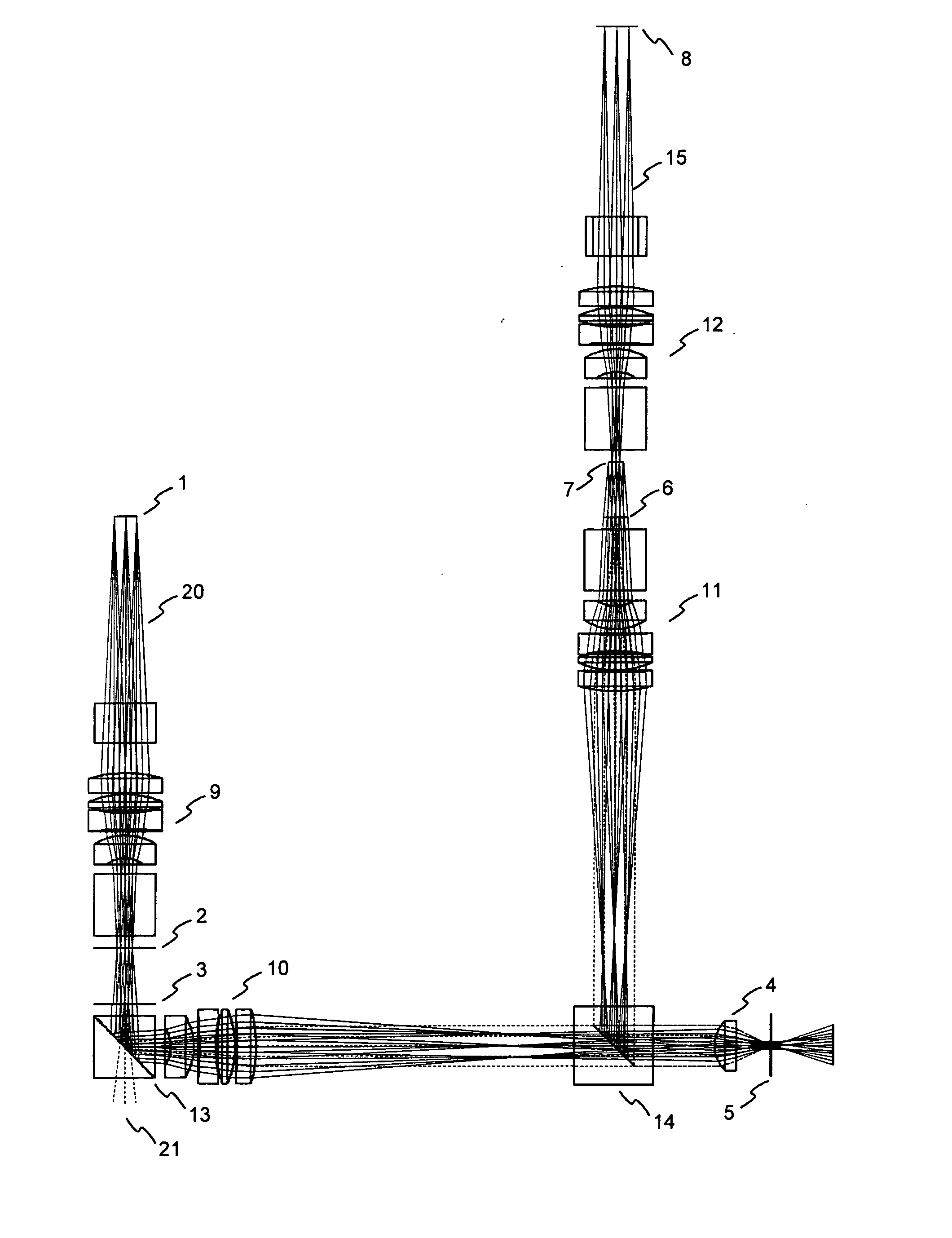
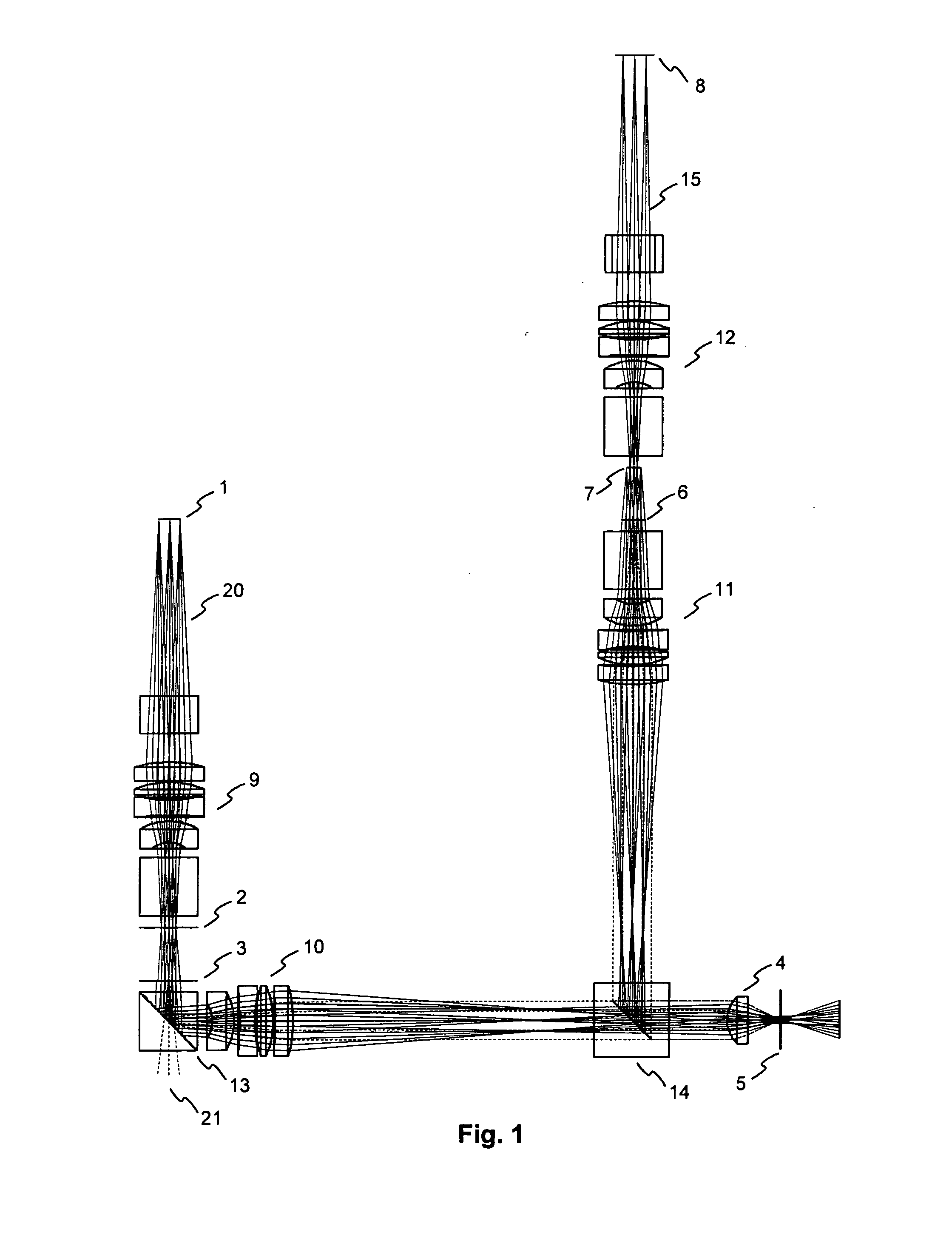
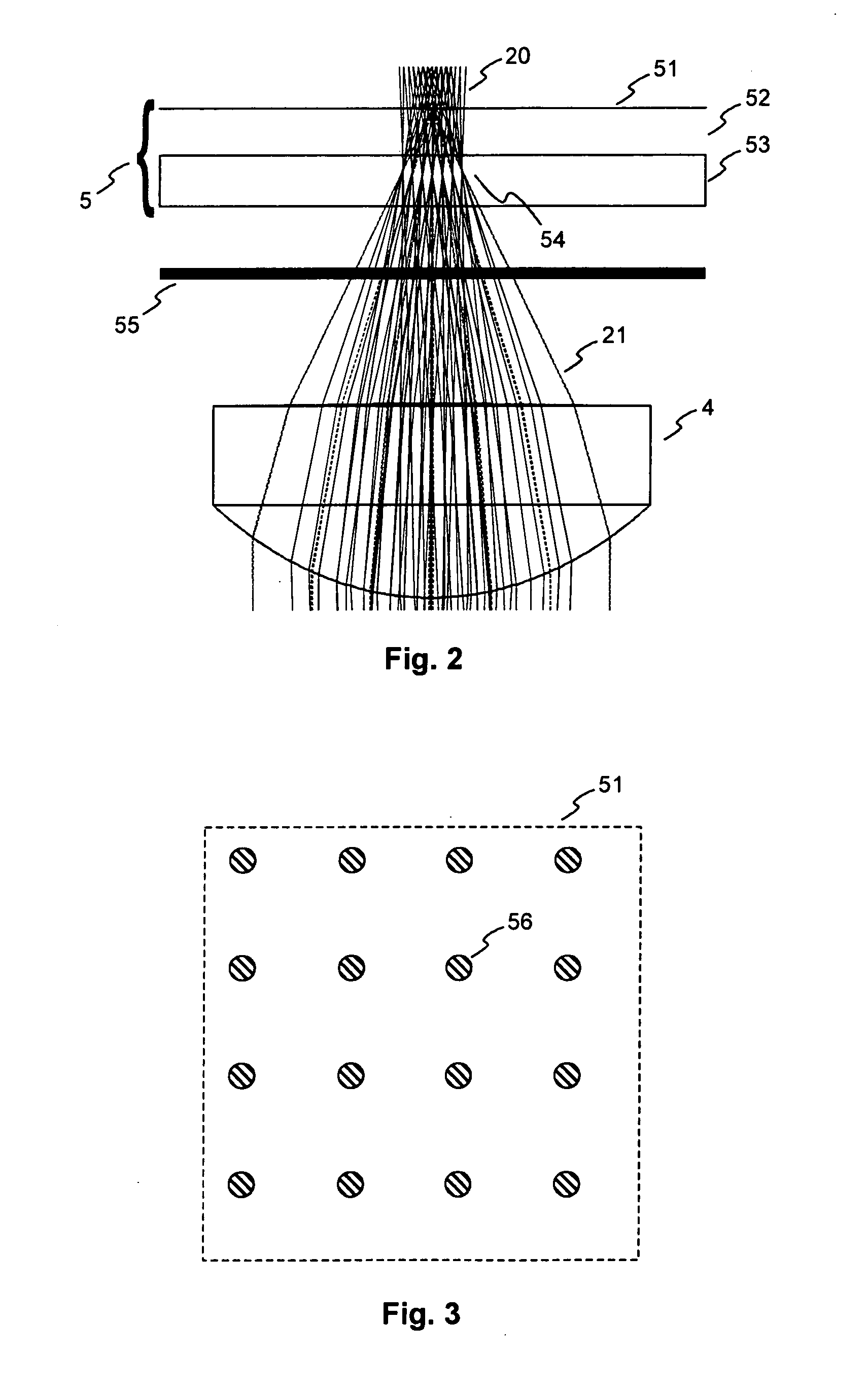
[0029]A coaxial holographic storage system according to the invention is schematically illustrated in FIG. 1. For recording a hologram an object beam 20 coming from an amplitude SLM 1 is Fourier transformed by a first long focal length Fourier objective 9. This objective is one of four identical long focal length Fourier objectives 9, 10, 11, 12. Located in the Fourier plane of the first long focal length Fourier objective 9 is an aperture 2 for low pass filtering the Fourier image in order to reduce the high spatial frequency components of the image. The plane of the aperture 2 does not coincide with the focal plane 3 of the second Fourier objective 10, where a reference beam 21 is coupled in. More details on the beam coupling will be given below with reference to FIG. 3. The distance between the Fourier plane and the focus of the reference beam 21 is reproduced at the position of the holographic material. Both beams 20, 21 pass through the second long focal length objective 10 and...


PUM

PropertyMeasurementUnit
sizeaaaaaaaaaa
thickaaaaaaaaaa
distanceaaaaaaaaaa

Abstract

An apparatus and a method for reading from and / or writing to holographic storage media using a coaxial arrangement of an object beam and one or more reference beams or a coaxial arrangement of a reconstructed object beam and one or more reference beams is proposed. A focus of the one or more reference beams within a holographic storage medium is shifted along the optical axis relative to a focus of the object beam or the reconstructed object beam.

Description

FIELD OF THE INVENTION[0001]The present invention relates to an apparatus and a method for reading from and / or writing to holographic storage media, and more specifically to an apparatus and a method using a coaxial arrangement of an object beam and one or more reference beams, which achieves an improved beam overlap within a holographic storage medium. The invention further relates to a holographic storage medium suitable for use in such an apparatus or with such a method.BACKGROUND OF THE INVENTION[0002]In holographic data storage digital data are stored by recording the interference pattern produced by the superposition of two coherent laser beams, where one beam, the so-called ‘object beam’, is modulated by a spatial light modulator and carries the information to be recorded. The second beam serves as a reference beam. The interference pattern leads to modifications of specific properties of the storage material, which depend on the local intensity of the interference pattern. R...

Claims


Application Information

Patent Timeline
Patent Type & Authority Applications(United States)
IPC IPC(8): G03H1/02G11B7/135G11B7/24044
CPCG11B7/0065G11B7/1353G03H1/10G11B7/24044G11B7/1398G03H1/02G03H1/22
Inventor KAUTNY, SZABOLCSBANKO, KRISZTIANSZARVAS, GABORKARPATI, ZOLTAN
Owner THOMSON LICENSING SA
Learn More