
Light conversion assembly, a lamp and a luminaire

a technology of light conversion assembly and light source, which is applied in the direction of point-like light source, semiconductor device of light source, lighting and heating apparatus, etc., can solve the problems of relatively large amount of different layers of luminescent material to be kept in stock, relative difficulty in manufacturing light emitters, and relatively high cost of characterizing and binning manufactured light emitters, etc., to achieve different blue light emission spectra

Active Publication Date: 2016-08-02
LUMILEDS
View PDF21 Cites 3 Cited by
  • Summary
  • Abstract
  • Description
  • Claims
  • Application Information

AI Technical Summary

Benefits of technology

[0006]It is an object of the invention to provide a color conversion assembly which allows the use of blue light emitting light sources which have slightly different blue light emission spectra.
[0018]Optionally, the first peak wavelength is in a range from 380 nanometer to 460 nanometer. Optionally, the first peak wavelength is in a range from 440 nanometers to 460 nanometers. If the first peak wavelength is in one of these ranges, still enough non-used wavelengths in the blue spectral range is available in which the light of the second spectral distribution may be emitted. Thus, a designer of the light conversion assembly is able to select the first luminescent material which has a light emission spectrum in the part of the blue spectral range which does not overlap with the first spectral distribution and which has a light absorption spectrum which fully overlaps with possible location of the first spectral distribution. Furthermore, such a position in the violet or blue spectral range allows a relatively large increase of peak wavelength from the first peak wavelength to the second peak wavelength, and, thus, a significant increase of the converted light when being expressed in lumen.
[0020]Optionally, the first layer is in direct contact with the light source. If the first layer is in direct contact with the light source it is easier to obtain a full conversion of light of the first spectral distribution. This optional embodiment prevents the leakage of light in between the light source and the first layer. Furthermore, the size of the first layer may be kept relatively small which saves materials.
[0021]Optionally, a gap is present between the first layer and the second layer. In other words, the second layer is arranged in a remote or vicinity configuration which means that the second layer is not in direct contact with the first layer. The gap prevents that the second layer receives heat from the first layer (and vice versa) as the result of conduction of heat. It is often advantageous to prevent that the second luminescent material in the second layer becomes too hot, because this may damage the second luminescent material and influence the efficiency of the second luminescent material in a negative way. Furthermore, in specific vicinity configurations, the total efficiency of the light conversion assembly may be higher.
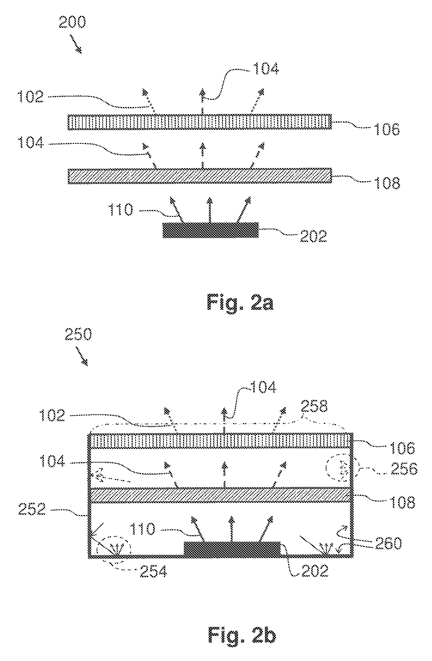
[0023]Walls of the reflective light mixing chamber reflect light which impinges on them and, thus, recycles light which is emitted or reflected by one of the components of the light conversion assembly in a wrong direction (which is not the direction of the light exit window). The light source may emit light towards the walls and the first layer or second layer may reflect a portion of the light which impinges on them. The efficiency of the light conversion assembly as a whole increases. Further, depending on the exact arrangement of the at least one of the light source, the first layer, the second layer within the reflective light mixing chamber, the light is better mixed and / or distributed such that a more homogeneous light output is obtained from the light conversion assembly.
[0027]The lamp according to the second aspect of the invention and the luminaire according to the third aspect of the invention provide the same benefits as the light conversion assembly according to the first aspect of the invention and have similar embodiments with similar effects as the corresponding embodiments of the light conversion assembly.

Problems solved by technology

However, during production of lighting assemblies that use a combination of a blue light source and a layer of luminescent material which partially converts the blue light to light of another color a problem arises.
It is relatively difficult to manufacture light emitters, for example LEDs, which all emit exactly the same blue light emission spectrum.
It is not acceptable to combine light emitters, which slightly deviate from each other, with only one type of a layer with one specific amount of luminescent material, because it would result in lighting assemblies that emit slightly different colors of light.
Characterizing and binning the manufactured light emitters is relatively expensive, and a relatively large amount of different layers with luminescent material need to be kept in stock which is also relatively expensive.

Method used


Image

  • Light conversion assembly, a lamp and a luminaire
  • Light conversion assembly, a lamp and a luminaire
  • Light conversion assembly, a lamp and a luminaire

Examples


Embodiment Construction

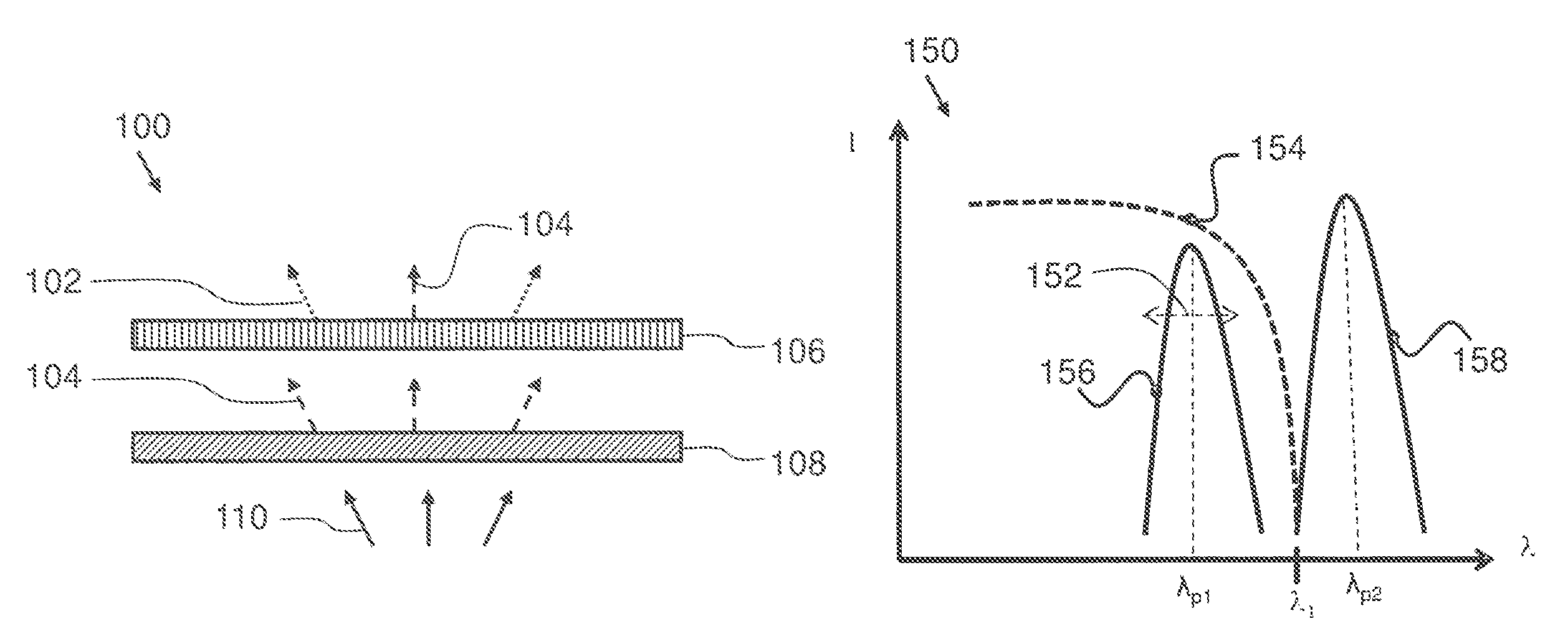
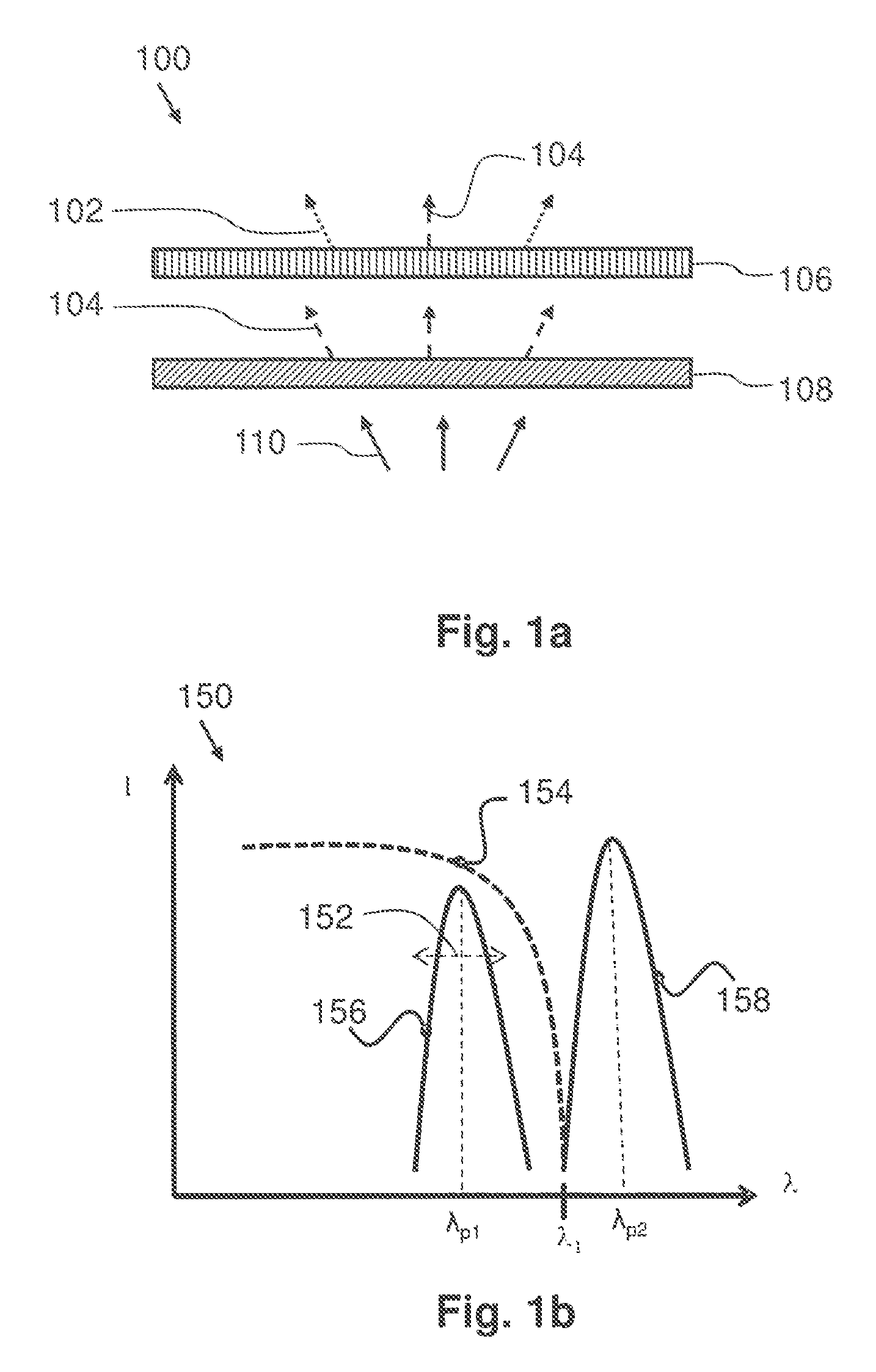
[0043]A first embodiment is shown in FIG. 1. FIG. 1a schematically shows a cross-sectional view of a light conversion assembly 100 according to the first aspect of the invention. A first layer 108 of the light conversion assembly 100 receives light 110 of a first spectral distribution. The first spectral distribution is in a violet or blue spectral range and the first spectral distribution has a first peak wavelength in the violet or blue spectral range. The first layer 108 comprises quantum dots which is a luminescent material. The quantum dots absorb light of the first spectral distribution and convert the absorbed light towards light 104 of a second spectral distribution. The second spectral distribution is in the blue spectral range and has a second peak wavelength which is a longer wavelength than the first peak wavelength. The first layer 108 is configured to fully convert the received light of the first spectral distribution towards light 104 of the second spectral distributi...


PUM


Abstract

A light conversion assembly 100, a lamp and a luminaire is provided. The light conversion assembly 100 comprises a first layer 108 and a second layer 106. The first layer 108 comprises first luminescent material. The first luminescent material comprises particles showing quantum confinement and have at least in one dimension a size in the nanometer range. The first layer is arranged to receive light 110 from a light source emitting light of a first spectral distribution in a violet or blue spectral range. The first spectral distribution has a first peak wavelength. The first layer 108 is configured to convert substantially all the received light 110 towards light 104 of a second spectral distribution in the blue spectral range, independently of the position of first spectral distribution in the violet or blue spectral range. The second spectral distribution has a second peak wavelength which is a longer wavelength than the first peak wavelength. The second layer 106 comprises a second luminescent material. The second layer is arranged to receive light 104 of the second spectral distribution and is configured to at least partially convert the received light 104 towards light 102 of a third spectral distribution being different from the first spectral distribution and the second spectral distribution.

Description

CROSS-REFERENCE TO PRIOR APPLICATIONS[0001]This application is the U.S. National Phase application under 35 U.S.C. §371 of International Application No. PCT / IB13 / 052820, filed on Apr. 9, 2013, which claims the benefit of U.S. Provisional Patent Application No. 61 / 623,609, filed on Apr. 13, 2012. These applications are hereby incorporated by reference herein.FIELD OF THE INVENTION[0002]The invention relates to light conversion assemblies for converting light emitted by a light source towards light of a different color.BACKGROUND OF THE INVENTION[0003]In several applications a Light Emitting Diode (LED) that emits blue light is combined with luminescent material which converts a part of the blue light towards light of another color, for example, to yellow, orange or red light. Often not all blue light is converted to the another color, because white light must be emitted by an assembly of the LED and the luminescent material. The amount and characteristics of the luminescent material ...

Claims


Application Information

Patent Timeline
Patent Type & Authority Patents(United States)
IPC IPC(8): F21V9/00F21K99/00H01J61/44H01L33/50F21V9/08F21V9/16F21Y101/02
CPCF21K9/56F21K9/54F21V9/08F21V9/16H01J61/44H01L33/504F21Y2101/02F21Y2101/025F21K9/62F21Y2115/30F21K9/64F21Y2115/10F21V9/32F21V9/38
Inventor HIKMET, RIFAT ATA MUSTAFAVAN BOMMEL, TIES
Owner LUMILEDS
Learn More