
Lighting umbrella

a technology for umbrellas and led lamps, applied in the field of sunshade umbrellas, can solve the problems of reducing the strength of the ribs, affecting the brightness of the sunshade umbrella, and consuming time and labor, so as to avoid the effect of decreasing the brightness, less time and labor, and convenient mounting

Active Publication Date: 2016-08-09
LINHAI ZHONGTIAN ELECTRONICS APPLIANCE CO LTD
View PDF13 Cites 2 Cited by
  • Summary
  • Abstract
  • Description
  • Claims
  • Application Information

AI Technical Summary

Benefits of technology

[0015]With rational structure design, by providing light guide bars on the short ribs and making the SMD LED lamps cling to the light guide bars, a light band is formed through continuous refraction and reflection to realize the purposes of lighting and beautifying the environment in night; connecting a plurality of light guide bars in series in coordination with the power supply to guide light for the long ribs effectively avoids decreasing the brightness due to too long light guide bars; and both the assembly and the maintenance are more convenient and less time and labor consuming.

Problems solved by technology

However, during the production, the necessity of drilling on every one of the ribs makes the strength of the ribs degraded so that the sunshade umbrellas are likely to be damaged.
Mounting these LED lamp beads into the bores is both time and labor consuming.
Furthermore, to realize the desired lighting effect, a lot of lamp beads are needed.
However, the excessive lamp beads lead to excessive circuits, causing the mounting more complicated.
On the other hand, once an individual lamp bead burns or an individual circuit breaks down, the use of the whole umbrella will be influenced and the maintenance is particularly inconvenient.

Method used


Image

  • Lighting umbrella
  • Lighting umbrella
  • Lighting umbrella

Examples


Embodiment Construction

[0031]The utility model will be further described in details as below with reference to the accompanying drawings.

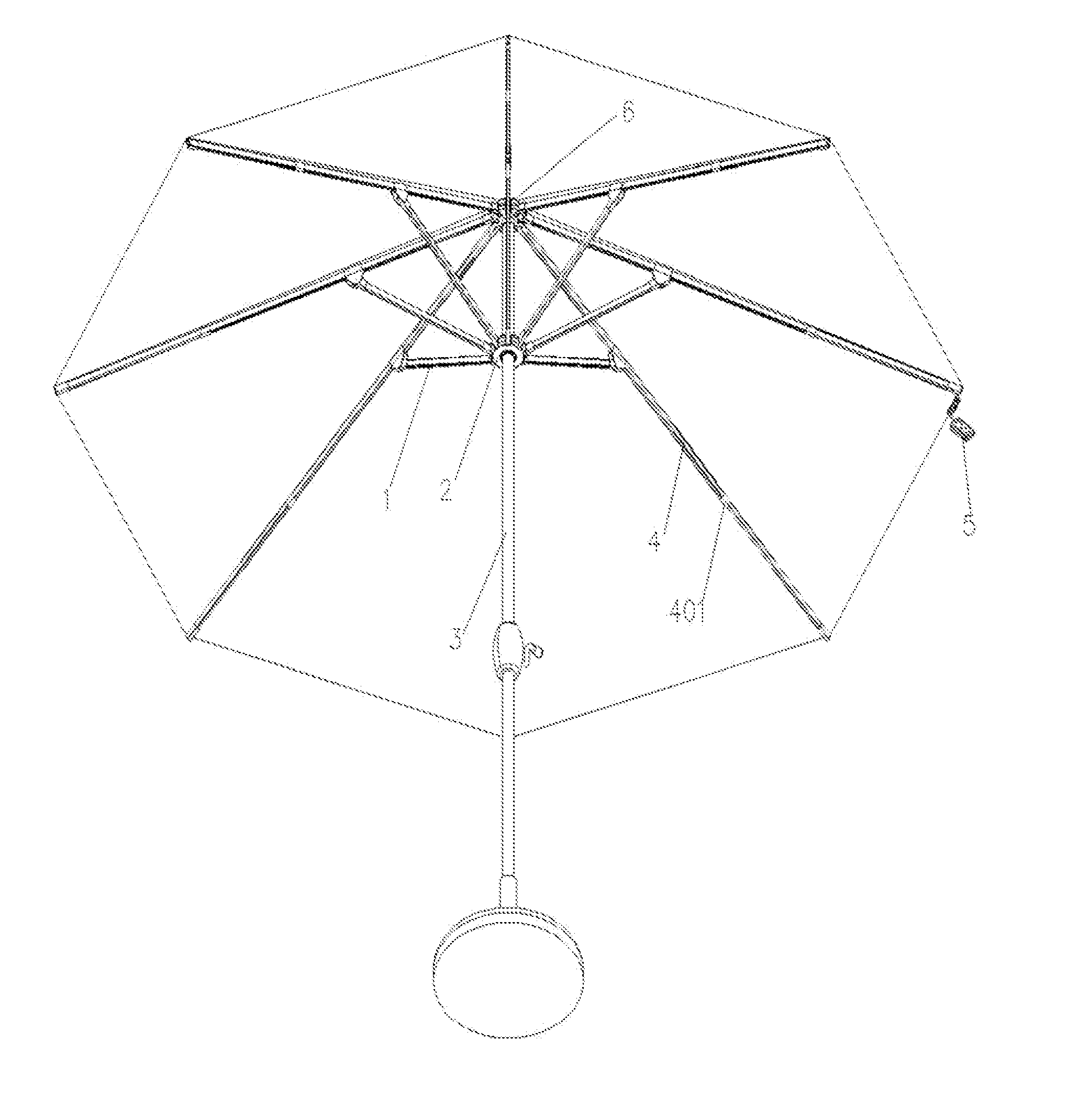
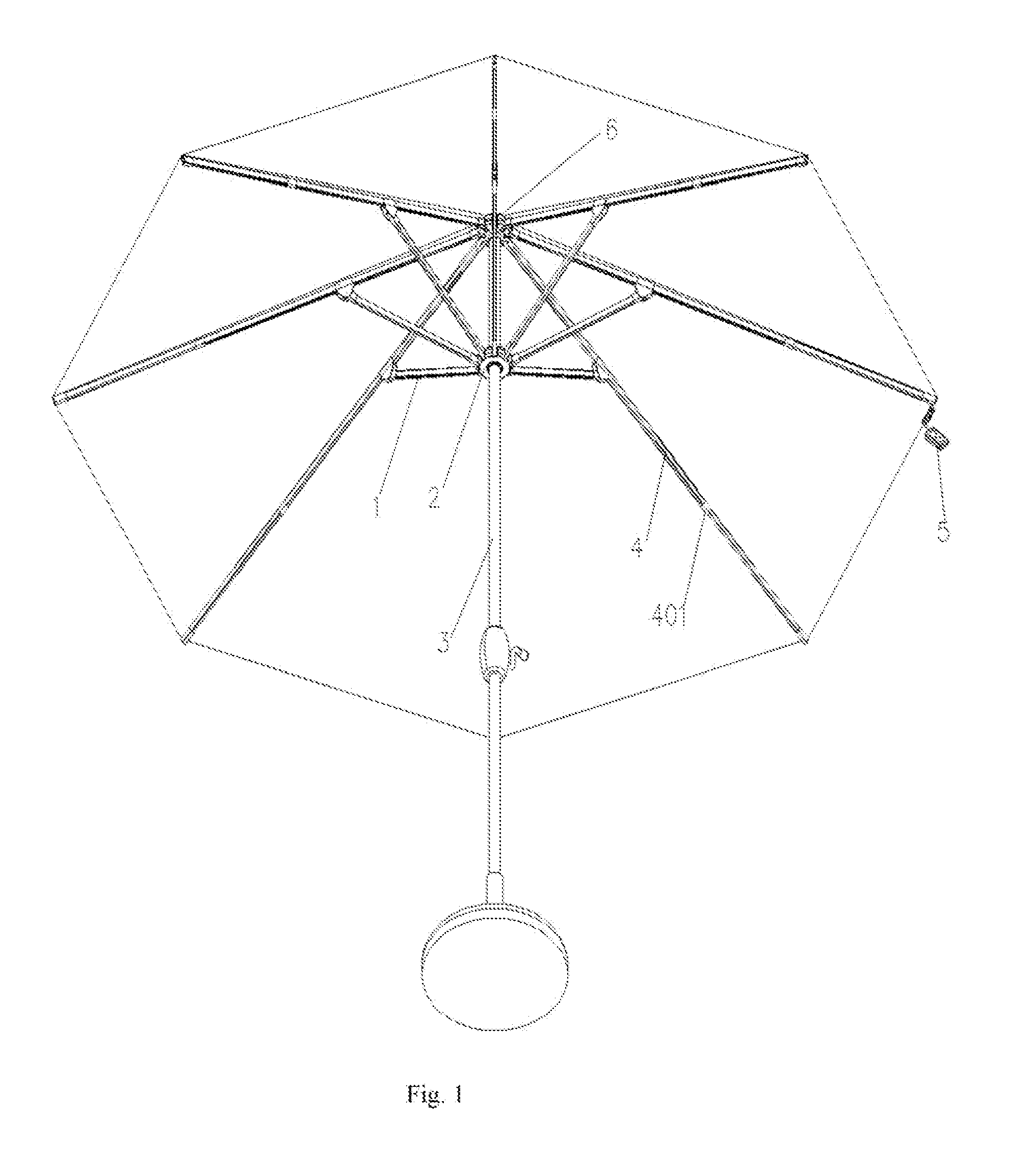
[0032]A novel lighting umbrella is provided, including a lower hub 2, an upper hub 6 secured on the top of a shaft 3, and ribs, one end of each of long ribs 4 being articulated with the upper hub 6 while the other end thereof supporting a panel, one end of each of short ribs 1 being articulated with the lower hub 2 while the other end thereof being articulated with the middle portion of one of the long ribs 4. A notch 101 is formed in one or both of the long ribs 4 and the short ribs 1. There may be one or two notches 101 in each of the long ribs 4 or the short ribs 1, each notch 101 having a light emitting device provided therein. The light emitting device comprises a light guide bar 14 clamped inside the notch 101, and a clamping flange 102 that can clamp the light guide bar 14 to prevent it from falling off is provided on the edge of the notch 101. The light guide bar...


PUM


Abstract

A novel lighting umbrella, comprising a lower hub (2) and an upper hub (6) secured on the top of a shaft (3), one end of each of long ribs (4) being articulated with the upper hub (6) while the other end thereof supporting a panel, one end of each of short ribs (1) being articulated with the lower hub (2) while the other end thereof being articulated with the middle portion of one of the long ribs (4), characterized in that a notch (101) having a light emitting device therein is formed in one or both of the long ribs (4) and the short ribs (1); the light emitting device comprises a light guide bar (14) clamped inside the notch (101) and provided with a light source on its end surface; and the light source is secured on a fixed base (7) that is fixedly connected to the ribs and sleeved with a stopper (8) for protection.

Description

CROSS-REFERENCE TO RELATED APPLICATIONS[0001]This application is a continuation of, and claims priority to, Chinese Patent Application No. 201410832999.6 with a filing date of Dec. 29, 2014. The content of the aforementioned application, including any intervening amendments thereto, is incorporated herein by reference.TECHNICAL FIELD[0002]The utility model relates to the technical field of sunshade umbrellas, in particular to a novel lighting umbrella.BACKGROUND OF THE INVENTION[0003]Sunshade umbrellas are leisure products frequently used in people's daily life. At present, there are a wide variety of sunshade lighting umbrellas among which those having a plurality of LED lamp beads mounted on the ribs are commonly used. However, during the production, the necessity of drilling on every one of the ribs makes the strength of the ribs degraded so that the sunshade umbrellas are likely to be damaged. Mounting these LED lamp beads into the bores is both time and labor consuming. Further...

Claims


Application Information

Patent Timeline
Patent Type & Authority Patents(United States)
IPC IPC(8): A45B3/04F21V1/06F21V33/00F21V8/00F21V23/04F21V19/00
CPCA45B3/04F21V19/005F21V23/0414F21V33/0004G02B6/0096A45B2200/1018F21Y2101/00A45B25/02F21Y2115/10
Inventor JIN, SHIMIN
Owner LINHAI ZHONGTIAN ELECTRONICS APPLIANCE CO LTD
Learn More