
Brake system

a technology of brake system and braking method, which is applied in the field of brake system, can solve the problems of vehicle occupants' discomfort, change in braking method, and so as to reduce the discomfort of the driver and reduce the change in vehicle stopping posture during the switching

Active Publication Date: 2016-08-09
TOYOTA JIDOSHA KK
View PDF16 Cites 7 Cited by
  • Summary
  • Abstract
  • Description
  • Claims
  • Application Information

AI Technical Summary

Benefits of technology

The system reduces driver discomfort by ensuring smooth transitions between braking modes, maintaining vehicle posture, and optimizing energy use by minimizing hydraulic pressure on wheels without electric parking brakes, allowing for comfortable brake pedal operation and efficient battery usage.

Problems solved by technology

Therefore, where a vehicle is decelerated and stopped on a low-μ slope, a stable vehicle stopping posture can be obtained with four wheels, but with two wheels, the vehicle stopping posture changes, and the vehicle occupants can feel uncomfortable.
Further, when switching is performed from hydraulic braking force control of four wheels to braking by the two-wheel electric parking brake, a switching shock (vibrations) caused by a change in the number of the braked wheels and a change in the braking method can occur.
Therefore, the stroke of the brake pedal is made difficult, and the driver can feel uncomfortable.

Method used


Image

  • Brake system
  • Brake system
  • Brake system

Examples


first embodiment

[0085]The first embodiment is explained below with reference to FIGS. 3 to 6. In the first embodiment, the case is considered in which the automatic maintenance control of the braking force, that is, the so-called BH, is performed as automatic braking force control when the vehicle is stopped. The BH also includes the case in which the braking force is maintained as a result of the ACC control. When the usual ACC is performed, brake control is executed with respect to all wheels. Where a predetermined period of time elapses after the vehicle has been stopped, the electric parking brake devices are automatically actuated and switched to parking brake control. In this case, for example, the switching is performed from four-wheel braking to two-wheel braking of the wheels on which the electric parking brake devices have been mounted. As mentioned hereinabove, in some cases, a switching shock (vibrations) caused by a change in the number of the braked wheels and a change in the braking ...

second embodiment

[0097]The second embodiment is explained below with reference to FIGS. 7 to 11. In the above-described first embodiment, the control is explained that is performed when a condition that the vehicle speed is equal to zero is fulfilled as the predetermined speed condition during the automatic braking force control, but in the second embodiment, an example is explained in which a control condition that a predetermined period of time has elapsed after the vehicle has been stopped is taken as the predetermined speed condition during the automatic braking force control.

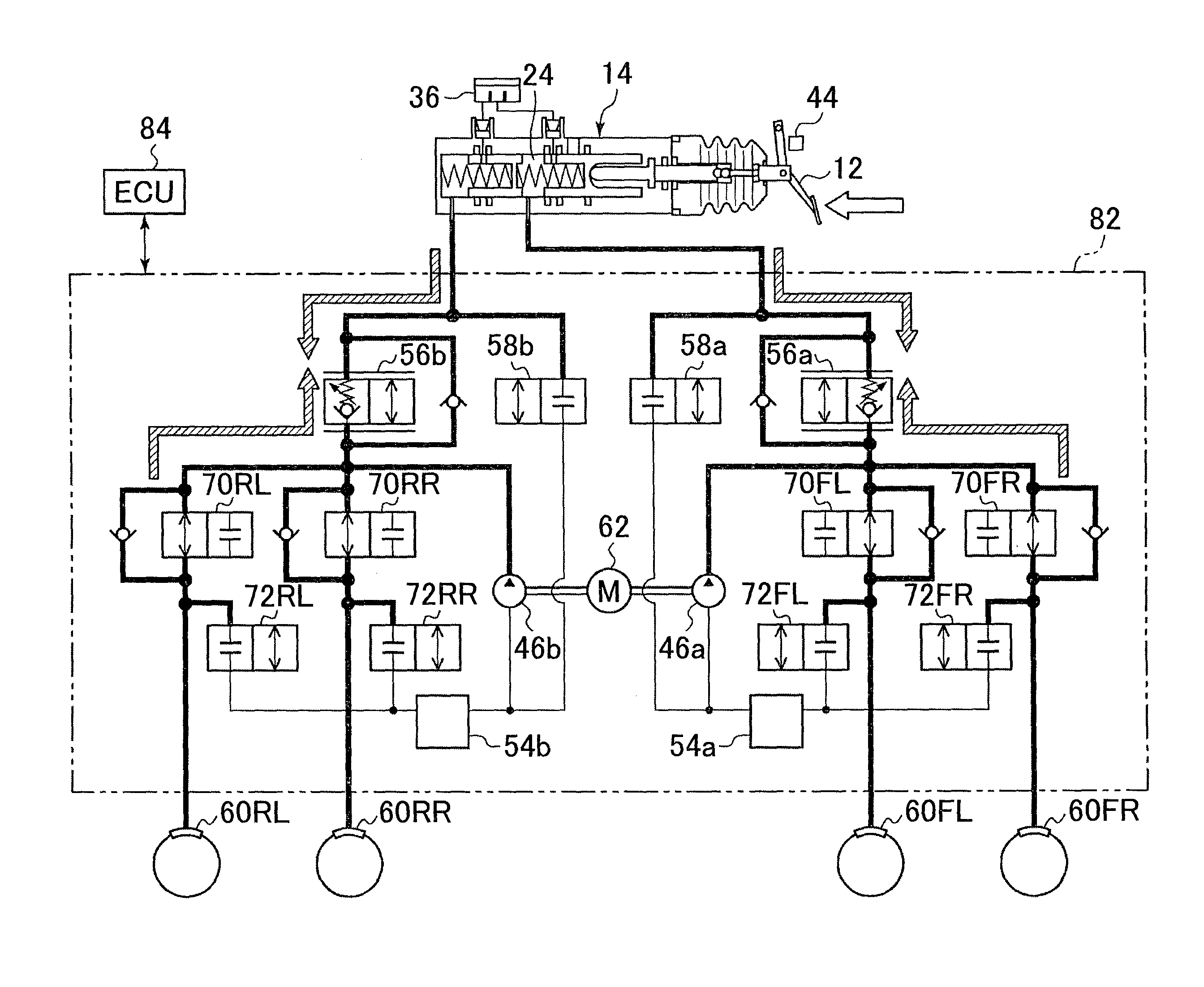
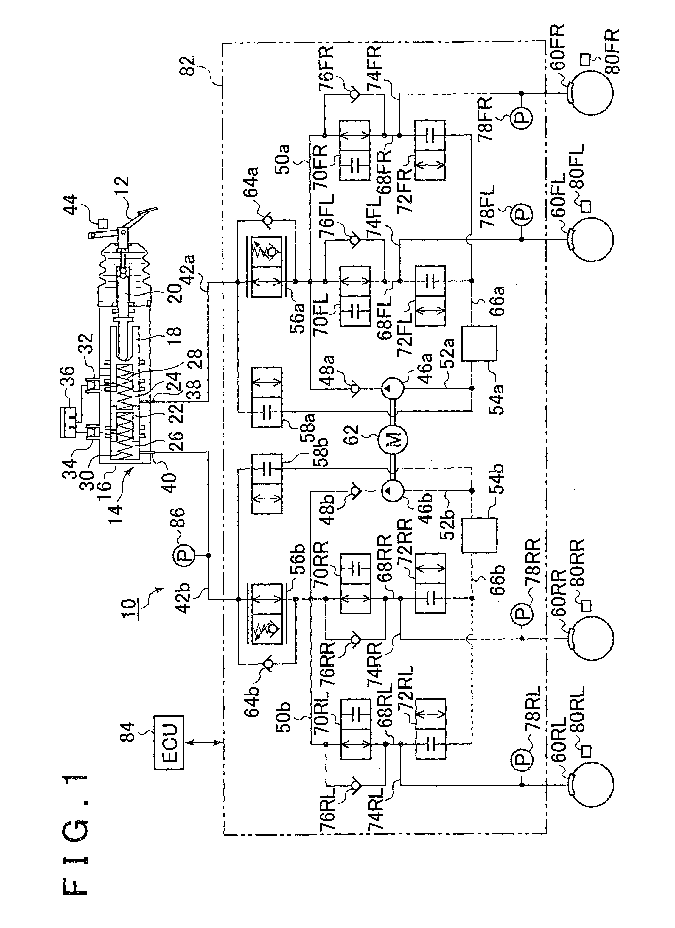
[0098]FIG. 7 shows the hydraulic pressure state when the brake system 10 executes the automatic braking force control. This state is basically the same as the hydraulic pressure state shown in FIG. 3. When the automatic braking force control is executed, the ECU 84 drives the motor 62 and causes the pumps 46a, 46b to discharge the working liquid in a state in which the linear control valves 56a, 56b are closed, the pressure...

third embodiment

[0110]The third embodiment is explained below with reference to FIGS. 12 to 14. In the above-described first embodiment and second embodiment, the control is explained in which the condition that the vehicle speed is equal to zero (stopped vehicle), or the condition that a predetermined period time has elapsed after the vehicle speed has become zero (the vehicle has stopped) is taken as the predetermined speed condition during the automatic braking force control. In the third embodiment, a case is explained in which a control condition that the vehicle speed is equal to or lower than a predetermined speed is taken as the predetermined speed condition during the automatic braking force control.

[0111]The hydraulic pressure state when the brake system 10 executes the automatic braking force control (ACC control) is the same as the state shown in FIG. 7. Therefore, this state can be understood by referring to FIG. 7, and detailed explanation thereof is herein omitted. When the automatic...


PUM


Abstract

A brake, system includes a hydraulic brake that supplies a hydraulic pressure to a cylinder provided correspondingly to each wheel mounted on a vehicle, thereby pressing friction members against the wheels and applying a hydraulic braking force; an electric brake that is mounted on at least one wheel from among the wheels and applies a braking force to the wheel by drive of an electric actuator; and a controller that executes control of supply of hydraulic pressure to each wheel cylinder by the hydraulic brake and operation control of the electric brake, regardless of a braking request by a driver, and causes a transition from hydraulic braking force control of all of the wheels to hydraulic braking force control of the wheel on which the electric brake has been mounted, when a speed of the vehicle satisfies a condition during the hydraulic braking force control of all of the wheels.

Description

BACKGROUND OF THE INVENTION[0001]1. Field of the Invention[0002]The invention relates to a brake system, and more particularly to a brake system in which cooperation control of a hydraulic braking device and an electric parking brake device is performed.[0003]2. Description of Related Art[0004]A disk brake device and a drum brake device are available as brake devices for vehicles. The brake device of each type is configured such that the hydraulic pressure corresponding to the working liquid delivered from a master cylinder according to the depression amount of a brake pedal operated by a driver is supplied to the wheel cylinder of the disk brake device or drum brake device, thereby generating a braking force (referred to hereinbelow as hydraulic braking force control). A parking brake device that maintains the stopping state of a vehicle when the vehicle is stopped for a comparatively long time or parked is also available. The parking brake device is usually of a manual type in whi...

Claims


Application Information

Patent Timeline
Patent Type & Authority Patents(United States)
IPC IPC(8): G06F7/70B60T8/48B60T7/12B60T13/58
CPCB60T7/12B60T13/588B60T8/4872
Inventor YAMAMOTO, SHINSUKEOMINE, HIROSHI
Owner TOYOTA JIDOSHA KK
Learn More