
Reciprocating pump cavitation detection and avoidance

a technology of cavitation detection and avoidance, applied in the direction of pump control, positive displacement liquid engine, machines/engines, etc., can solve the problems of destroying the pump housing and/or associated components, causing problems, and causing material to be removed and damaged

Active Publication Date: 2016-08-09
BJ ENERGY SOLUTIONS LLC FORMERLY TES ASSET ACQUISITION LLC
View PDF20 Cites 125 Cited by
  • Summary
  • Abstract
  • Description
  • Claims
  • Application Information

AI Technical Summary

Benefits of technology

The invention is about detecting cavitation in a pump. The system uses a sensor to measure pressure, an accelerometer to detect vibration, and a timing marker to monitor pump speed. The data processor compares the measured pressure with a predetermined pressure to check for cavitation. If cavitation is detected, the processor can alert an operator and adjust pump parameters to try to fix it. This helps to prevent damage to the pump from cavitation.

Problems solved by technology

If these implosions occur in close proximity to the pump housings or valve surfaces, they will start to impinge the material, causing material to be removed and damaged.
Cavitation can cause permanent damage and, if not prevented in time, can lead to complete destruction of the pump housing and / or associated components.
However, this has proven problematic.
There is a wide variety of vibration or acoustic signal responses that relate to a variety of abnormal conditions, which makes it difficult to differentiate between cavitation, valve wear, seal failure, or other conditions.

Method used


Image

  • Reciprocating pump cavitation detection and avoidance
  • Reciprocating pump cavitation detection and avoidance
  • Reciprocating pump cavitation detection and avoidance

Examples


Embodiment Construction

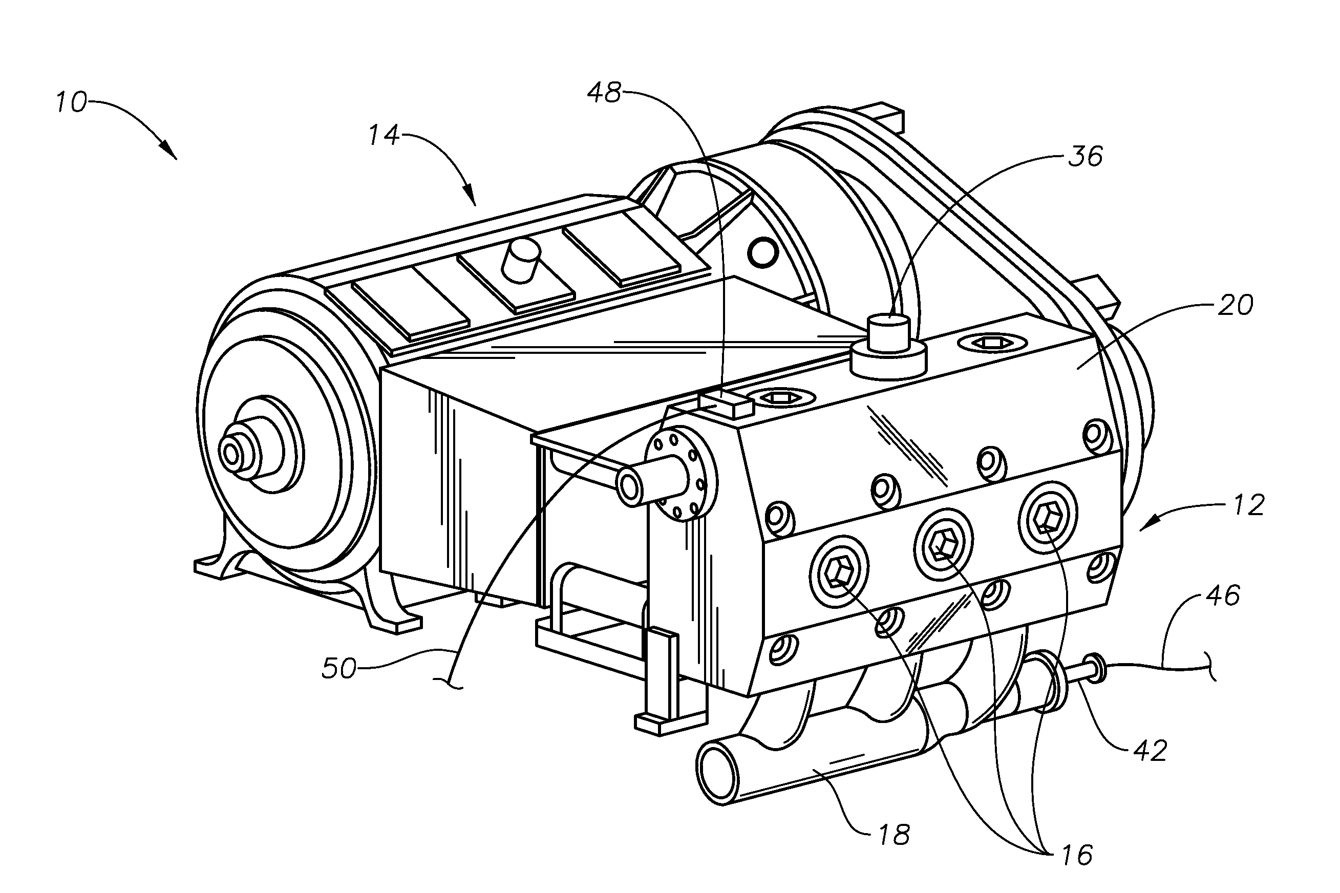
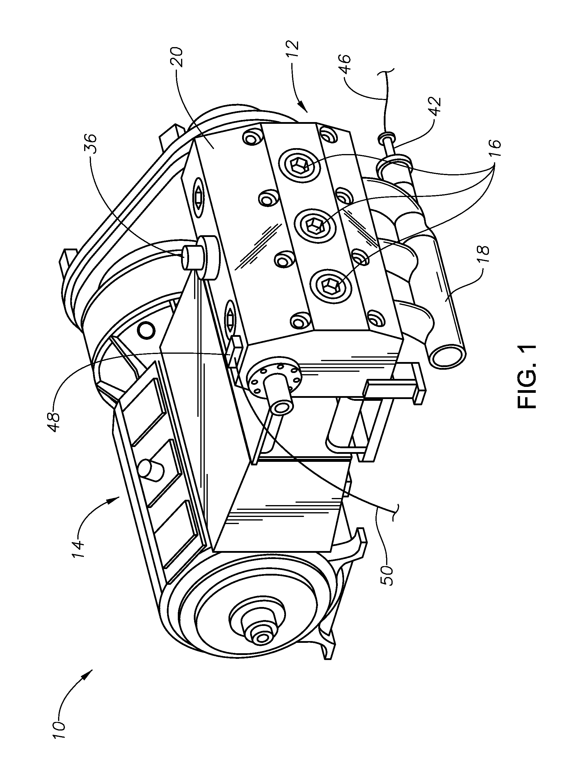
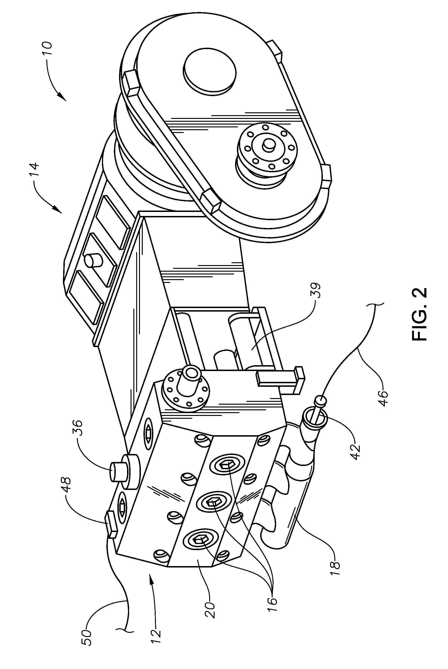
[0023]FIGS. 1-4 illustrate an exemplary reciprocating pump 10 which broadly includes a fluid end 12, which draws fluid into the pump 10 and expels it, and a power end 14, which receives power from an associated motor or other prime mover and transmits this power to the fluid end 12. In the depicted embodiment, the pump 10 is a triplex pump having three pistons, which are evidenced by the cylinder heads 16 in FIGS. 1-2. A suction manifold 18 leads into the fluid end 12 of the pump 10.

[0024]The cross-sectional view of FIG. 3 illustrates a cylinder housing 20 for the fluid end 12 which encloses a valve piston chamber 22 within which a plunger 24 is axially moveable in a reciprocating manner, as driven by a crankshaft. Although only a single plunger 24 is visible in FIG. 3, it should be understood that there are actually three plungers 24 within the housing 20. This reciprocating movement causes an intake valve 26 and an exhaust valve 28 to be opened and closed as fluid is pumped from t...


PUM


Abstract

Systems and methods for detecting cavitation in a reciprocating positive displacement pump. Fluid pressure proximate the pump's suction manifold is compared to a predetermined pressure that would be conducive to cavitation. If the detected pressure approximates the predetermined pressure, the presence of cavitation is confirmed via correlation of increased vibration.

Description

BACKGROUND OF THE INVENTION[0001]1. Field of the Invention[0002]The invention relates generally to reciprocating pumps. In particular aspects, the invention relates to systems and methods for detecting and monitoring abnormal conditions within a pump, including cavitation.[0003]2. Description of the Related Art[0004]Reciprocating positive displacement pumps used in the well service industry and drilling mud pump industry are exposed to high pressure, high flow rate and abrasive fluids (slurry) for the purpose of fracturing, drilling and so forth. Reciprocating pumps can be single or double acting pumps with pistons that are driven by a crankshaft that is actuated by a motor. Reciprocating positive displacement pumps have at least one piston cylinder, but often have multiple cylinders, such as three-cylinder (triplex) and five-cylinder (quintuplex) configurations.[0005]Cavitation affects reciprocating pumps during operation. Cavitation occurs when actual pressure reaches the vapor pr...

Claims


Application Information

Patent Timeline
Patent Type & Authority Patents(United States)
IPC IPC(8): F04B51/00F04B49/06
CPCF04B49/065F04B51/00
Inventor JAEGER, THOMASCHRISTIAN, ASHLEYGRIFFITH, GREGORY E.SINGH, GULSHANLATAQUIN, MICHAEL
Owner BJ ENERGY SOLUTIONS LLC FORMERLY TES ASSET ACQUISITION LLC
Learn More