
Valve for roof vent

a vent and valve technology, applied in ventilation systems, lighting and heating apparatus, heating types, etc., can solve problems such as unoptimized gooseneck traps, and achieve the effect of preventing backflow

Active Publication Date: 2016-08-16
RECTORSEAL LLC
View PDF241 Cites 12 Cited by
  • Summary
  • Abstract
  • Description
  • Claims
  • Application Information

AI Technical Summary

Benefits of technology

These valve systems effectively prevent backflow of odors and gases, ensuring proper drainage and venting, even in challenging installations, while maintaining flow efficiency and reliability.

Problems solved by technology

In many applications, however, particularly where access is difficult or where drainage is infrequent, gooseneck traps are not optimal due to insufficient space to install and to inaccessability.

Method used


Image

  • Valve for roof vent
  • Valve for roof vent
  • Valve for roof vent

Examples


Embodiment Construction

[0066]In the following discussion that addresses a number of embodiments and applications, reference is made to the accompanying drawings that form a part hereof, and in which is shown by way of illustration specific embodiments in which the embodiments described herein may be practiced. It is to be understood that other embodiments may be utilized and changes may be made without departing from the scope of the disclosure.

[0067]Various inventive features are described below that can each be used independently of one another or in combination with other features. However, any single inventive feature may not address all of the problems discussed above or only address one of the problems discussed above. Further, one or more of the problems discussed above may not be fully addressed by the features of each embodiment described below.

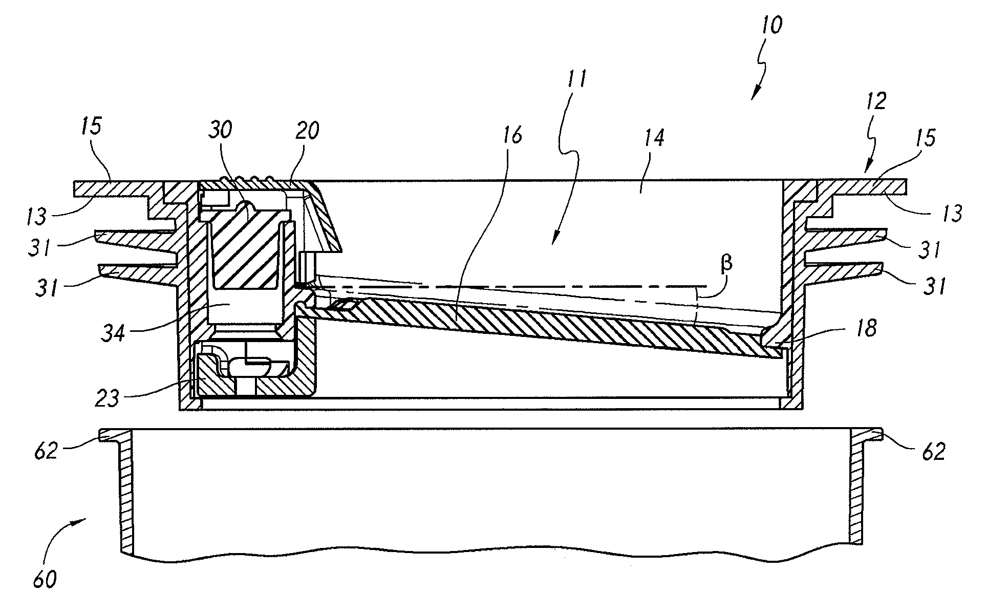
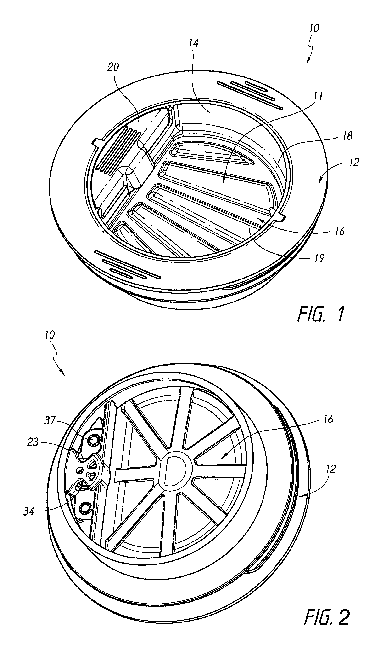
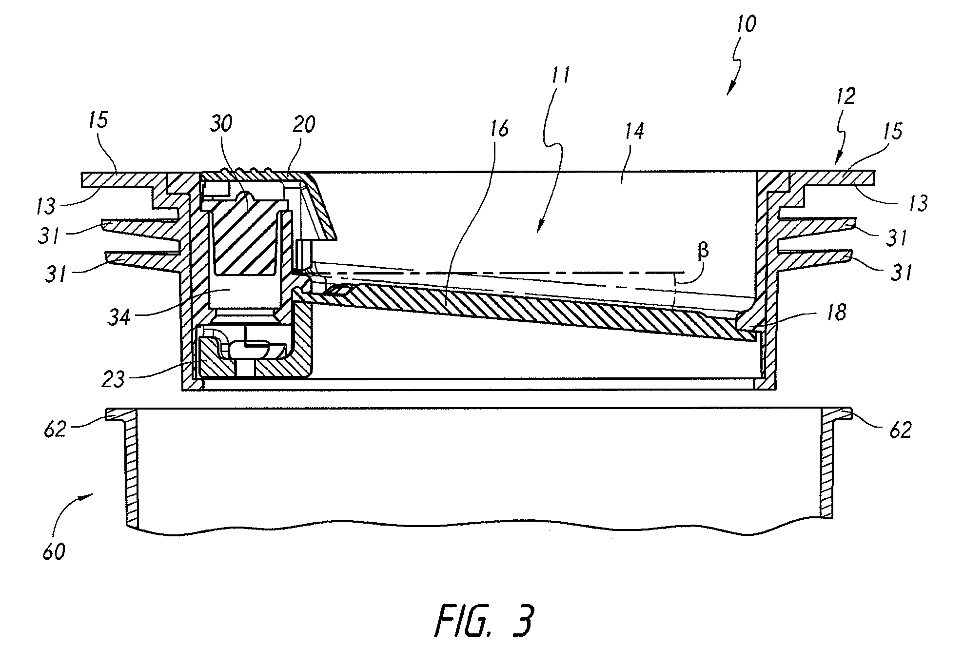
[0068]FIGS. 1-11 and the accompanying description below are directed to valves that prevent or substantially prevent the backflow of fluid (e.g., liquid o...


PUM


Abstract

A valve allows for drainage of gases while preventing backflow of gases from a drainage system through the valve. A drain can have a first, sealed position in which a component of the valve seals an opening through the valve and a second, open position in which the component of the valve is separated from the opening to allow a fluid to drain through the valve. When the fluid has drained through, the component of the valve can return to the closed position. The valve can include a pressure relief conduit to help equalize pressure across the valve and permit unrestrained draining of fluid through the valve. The valve can be positioned in a roof vent and can include a guard.

Description

CROSS-REFERENCE TO RELATED APPLICATIONS[0001]This application claims priority to U.S. Provisional Application Ser. No. 62 / 082,112, filed Nov. 19, 2014; U.S. Provisional Application Ser. No. 62 / 091,574, filed Dec. 14, 2014 and U.S. Provisional Application Ser. No. 62 / 094,860 filed Dec. 19, 2014; and[0002]this application is also a continuation in part of U.S. patent application Ser. No. 14 / 210,103, filed Mar. 13, 2014, and issued as U.S. Pat. No. 9,010,363, which is a continuation in part of U.S. patent application Ser. No. 14 / 082,018, filed Nov. 15, 2013, which claims priority to U.S. Provisional Application Ser. No. 61 / 878,349, filed Sep. 16, 2013 and U.S. Provisional Application Ser. No. 61 / 838,826, filed Jun. 24, 2013;[0003]the disclosures of all of the above-listed priority applications are hereby incorporated herein by reference in their entirety.INCORPORATION BY REFERENCE TO ANY PRIORITY APPLICATIONS[0004]Any and all applications for which a foreign or domestic priority claim ...

Claims


Application Information

Patent Timeline
Patent Type & Authority Patents(United States)
IPC IPC(8): F16K24/00F16K17/19F24F7/02F24F13/10E03F5/042F16K15/03E03C1/122E03F5/04F24F13/22
CPCF24F7/02F24F13/10E03F5/042F16K15/031F16K17/19E03C1/1225E03F2005/0417F24F2013/227Y10T137/6988Y10T137/7838
Inventor HUBER, KEVIN
Owner RECTORSEAL LLC
Learn More