
Commodity storage device

a storage device and commodity technology, applied in the field of commodity storage devices, can solve problems such as cost increase, and achieve the effect of cost reduction and cost reduction

Active Publication Date: 2016-08-16
FUJI ELECTRIC CO LTD
View PDF20 Cites 0 Cited by
  • Summary
  • Abstract
  • Description
  • Claims
  • Application Information

AI Technical Summary

Benefits of technology

The present invention provides a commodity storage device designed to securely extract commodities one by one while reducing costs. The device has multiple gate members and flapper members that enter the commodity storage passage to restrict the movement of commodities. Only when the first gate member is no longer in its position, the second gate member and the flapper member enter the passage to allow the most downstream commodity to be extracted. The technical effect of this invention is to provide a secure and cost-effective means of extracting commodities from a commodity storage column.

Problems solved by technology

This commodity storage device, therefore, has too many parts and requires expensive sensors and the like, leading to a cost increase.

Method used


Image

  • Commodity storage device
  • Commodity storage device
  • Commodity storage device

Examples


embodiment 1

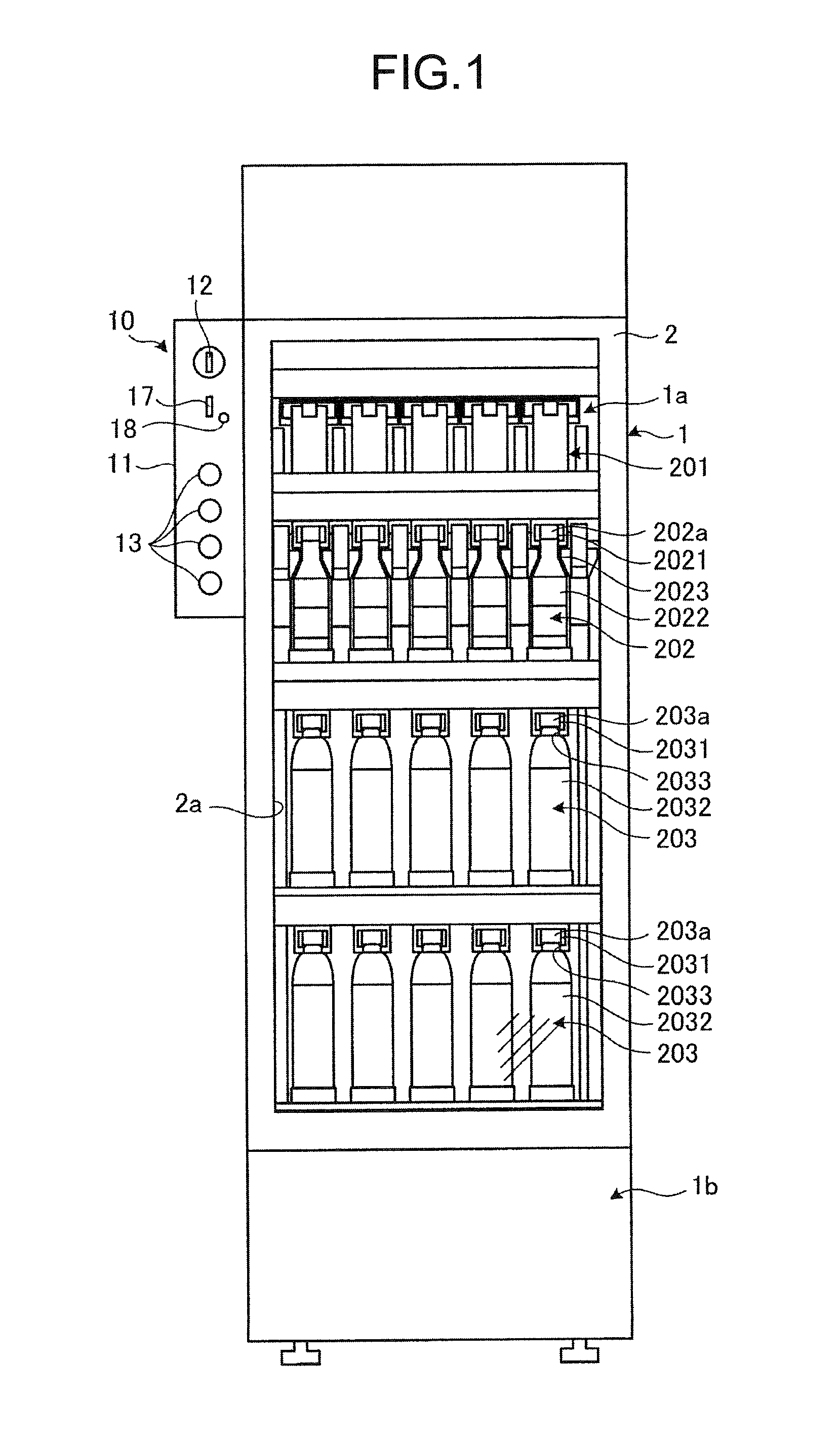
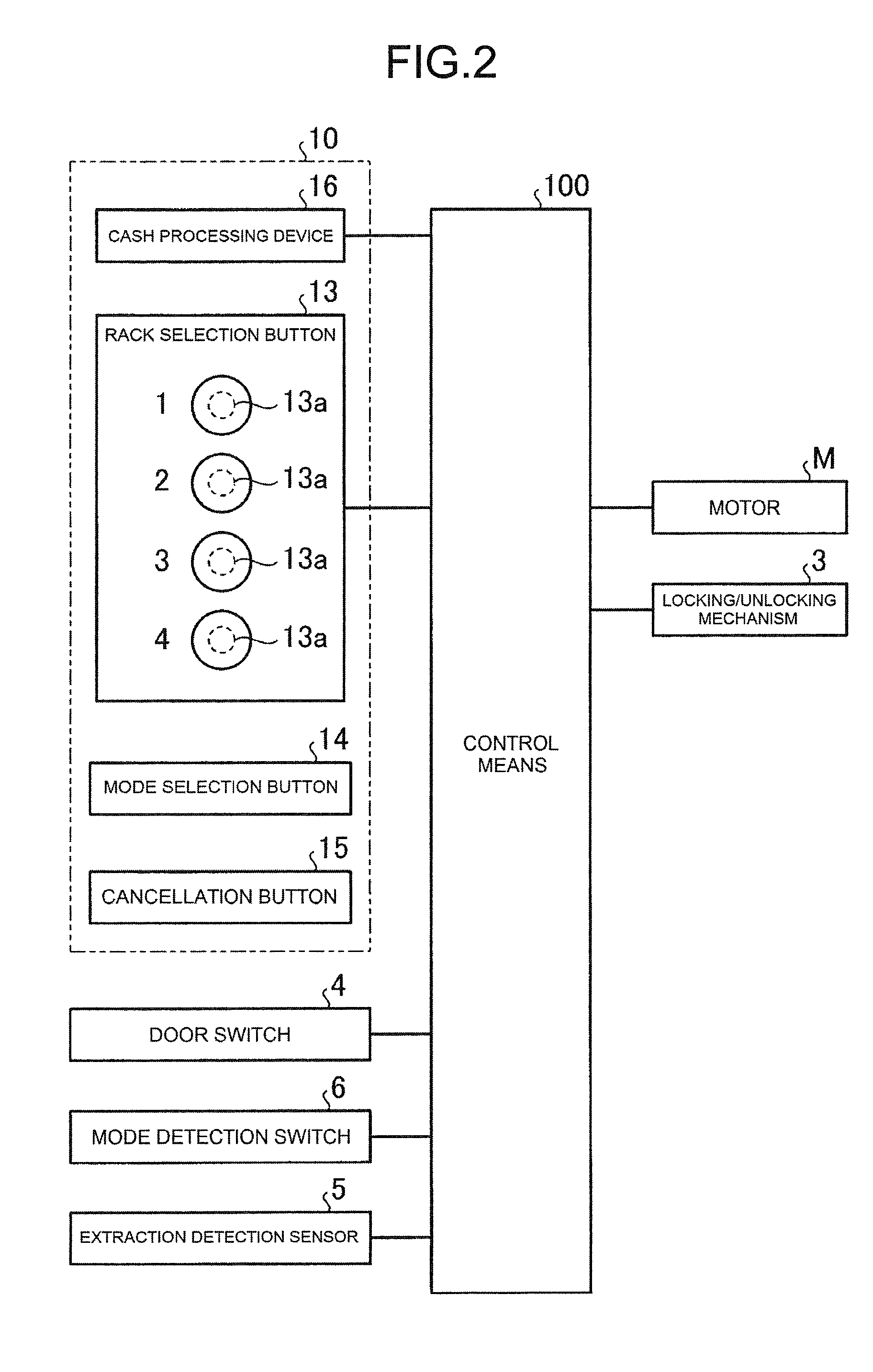
[0104]FIGS. 1 and 2 each show an automatic vending machine to which a commodity storage device of the present invention is applied, FIG. 1 being a front view and FIG. 2 a block diagram showing a control system. The automatic vending machine illustrated herein sells, for example, cooled or heated beverage commodities in cans, bottles, and plastic bottles, and has a main cabinet 1.

[0105]A canned beverage commodity is a commodity obtained by containing the beverage in a can 201 which is the container, and is in the shape of a cylinder with closed upper and lower surfaces. A bottled beverage commodity has the beverage contained in a bottle 202 which is the container, and is shaped to have a bulging portion 2023, the outer diameter of which increases gradually from a cap mount portion 2021 toward a body portion 2022, the cap mount portion 2021 having a cap 202a detachably mounted thereon. In addition, a plastic-bottled beverage commodity has the beverage contained in a plastic bottle 20...

embodiment 2

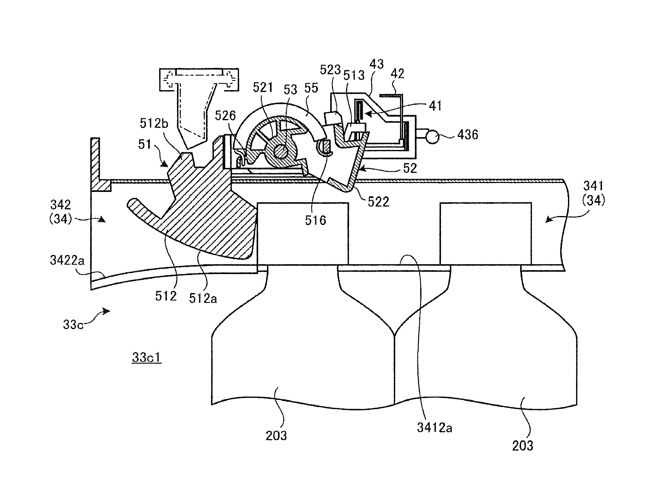
[0349]In the commodity storage device 21 of the present invention described above, the first slide plate 41 is located at the reference position during the normal state, to restrict the first gate member 51 from retreating from the corresponding commodity storage passage 33c1, preventing the commodities stored in the corresponding commodity storage column 33c from being extracted. Moreover, the first gate member 51 and the second gate member 52 can be brought into the free state by causing the corresponding switching cam member 45 to move the first slide plate 41 from the reference position. In this case, when the user extracts the foremost commodity from the commodity storage passage 33c1, the first gate member 51 retreats from the commodity storage passage 33c1, while the second gate member 52 enters the commodity storage passage 33c1. Once the second gate member 52 enters the commodity storage passage 33c1, the lock member 43 moves to above the second engaging piece 523 of the s...


PUM


Abstract

A commodity storage device has commodity storage columns defining respective commodity storage passages, in each of which commodities are stored upright in a line. The commodity storage device includes first gate members, each of which is provided turnably in such a manner as to enter and retreat from the corresponding commodity storage passage; second gate members, each of which is provided so as to be able to turn in conjunction with the corresponding first gate member in such a manner as to enter and in conjunction with the corresponding first gate member in such a manner as to enter and retreat from the corresponding commodity storage passage; and flapper members, each of which is provided turnably on a side wall forming the corresponding commodity storage passage in such a manner as to enter and retreat form the commodity storage passage.

Description

RELATED APPLICATIONS[0001]The present application is National Phase of International Application No. PCT / JP2013 / 064796 filed May 28, 2013, and claims priority from Japanese Applications No. 2012-123645, filed May 30, 2012 and No. 2012-123646, filed May 30, 2012, the disclosure of which is hereby incorporated by reference herein in its entirety.TECHNICAL FIELD[0002]The present invention relates to a commodity storage device that is applied to an automatic vending machine selling commodities such as canned beverages and plastic-bottled beverages.BACKGROUND ART[0003]Among the conventional automatic vending machines selling commodities such as canned beverages and plastic-bottled beverages, an automatic vending machine with a commodity storage device provided with a commodity storage column and a bucket for transporting commodities has been known. The commodity storage column is for storing a plurality of commodities in an arrangement. When a discharge device is driven, the commodity st...

Claims


Application Information

Patent Timeline
Patent Type & Authority Patents(United States)
IPC IPC(8): G07F11/16G07F11/42G07F11/60G07F11/18
CPCG07F11/60G07F11/18G07F11/42
Inventor YASAKA, YOSHIO
Owner FUJI ELECTRIC CO LTD
Learn More