Optical adjusting apparatus

a technology of optical adjustment and adjusting apparatus, which is applied in the direction of focusing aids, instruments, television systems, etc., can solve the problems of difficult accurate position control for auto-focusing, and achieve the effect of accurate control of position and slimming down the apparatus

Active Publication Date: 2016-08-16
SAMSUNG ELECTRONICS CO LTD
View PDF18 Cites 14 Cited by
  • Summary
  • Abstract
  • Description
  • Claims
  • Application Information

AI Technical Summary

Benefits of technology

[0008]The present disclosure has been developed in order to overcome the above drawbacks and other problems associated with the conventional arrangement. An aspect of the present disclosure is to provide an optical adjusting apparatus in which an image stabilization function and an auto focus function are integrated, and that can accurately control a position when auto-focusing, and can thus slim down the apparatus.
[0026]According to various embodiments of the present disclosure as described above, an optical adjusting apparatus is provided in which image stabilization function and auto focus function are integrated, can accurately control a position when auto focusing, and can be slimmed down.

Problems solved by technology

However, conventional optical pickup apparatuses typically use magnets for implementing the image stabilization function and the auto focus function, which makes accurate position control for auto-focusing difficult.

Method used


Image

  • Optical adjusting apparatus
  • Optical adjusting apparatus
  • Optical adjusting apparatus

Examples


Embodiment Construction

[0038]Hereinafter, certain exemplary embodiments of the present disclosure will be described in detail with reference to the accompanying drawings.

[0039]The matters defined herein, such as a detailed construction and elements thereof, are provided to assist in a comprehensive understanding of this description. Thus, it is apparent that exemplary embodiments may be carried out without those defined matters. Also, well-known functions or constructions are omitted to provide a clear and concise description of exemplary embodiments. Further, dimensions of various elements in the accompanying drawings may be arbitrarily increased or decreased to assist in a comprehensive understanding.

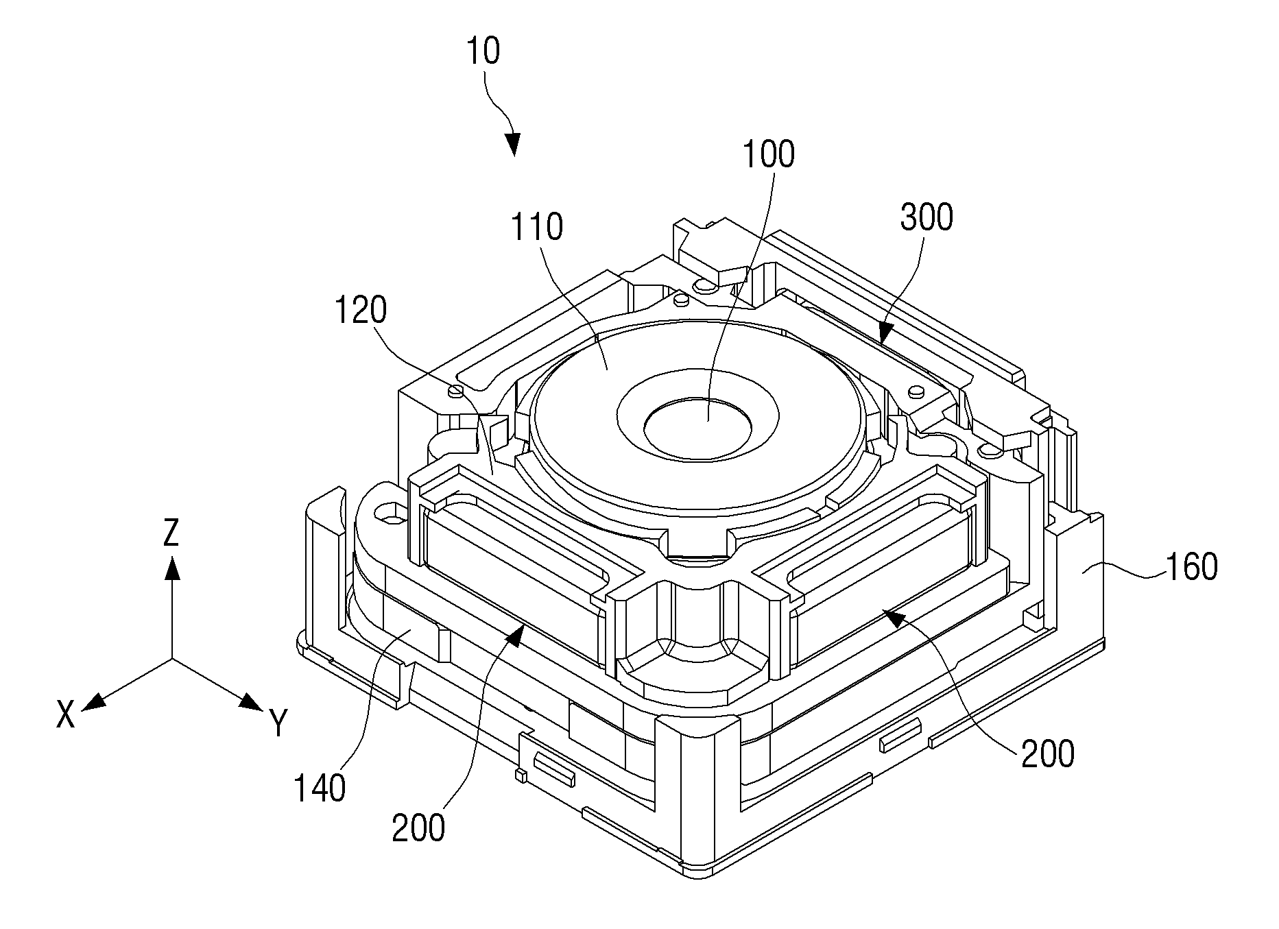
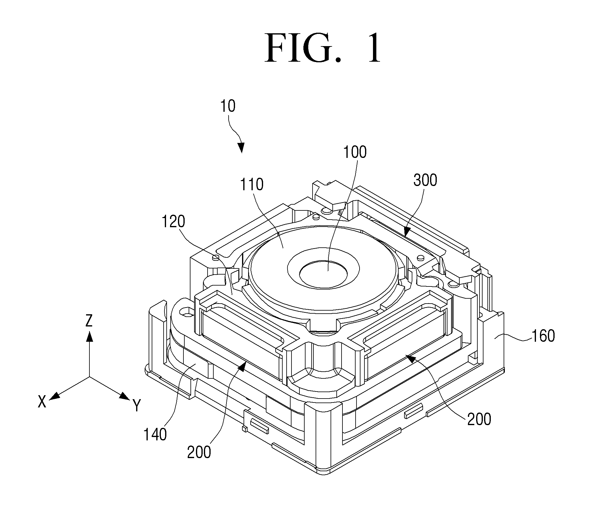
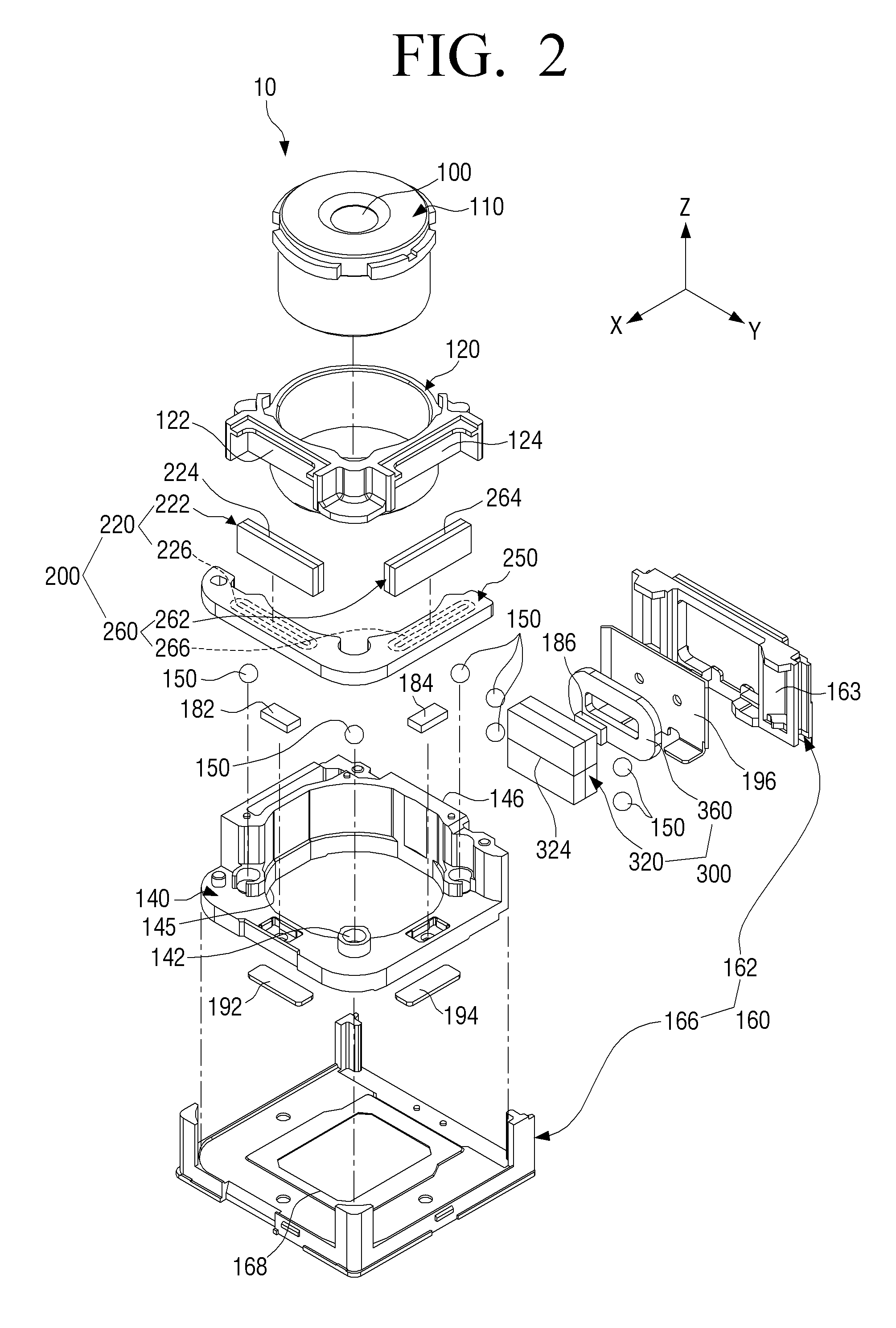
[0040]FIG. 1 is a perspective view illustrating an optical adjusting apparatus 10, according to an embodiment of the present disclosure. FIG. 2 is an exploded perspective view illustrating the optical adjusting apparatus 10 of FIG. 1.

[0041]Referring to FIGS. 1 and 2, an optical adjusting apparatus 10 includ...


PUM


Abstract

The present disclosure relates to an optical adjusting apparatus having an optical adjusting lens for image stabilization and auto focusing, which includes a lens holder that supports the optical adjusting lens; at least one image stabilization VCM actuator unit that moves the lens holder perpendicular to an optical axis of the optical adjusting lens, the image stabilization VCM actuator unit including a magnet with a neutral zone parallel to the optical axis; and an auto focusing VCM actuator unit that moves the lens holder in an optical axis direction, the auto focusing VCM actuator unit including a magnet with a neutral zone orthogonal to the optical axis.

Description

CROSS-REFERENCE TO RELAYED APPLICATIONS[0001]This application claims the priority benefit under 35 U.S.C. §119(a) from Korean Patent Application No. 10-2012-0144525 filed Dec. 12, 2012 in the Korean Intellectual Property Office, the disclosure of which is incorporated herein by reference in its entirety.BACKGROUND[0002]1. Field[0003]The present disclosure relates to an optical adjusting apparatus. More particularly, the present disclosure relates to an optical adjusting apparatus in which an image stabilization function and an auto focus function are integrated.[0004]2. Related Art[0005]In recent years, slimmer electronic devices such as smart phones, etc. have emerged as a major subject. To create slimmer electronic devices, various attempts to slim down a variety of parts disposed inside the electronic devices have been performed.[0006]Various attempts to slim down camera modules provided in the electronic device such as a smart phone, etc. have also been performed. For example, a...

Claims


Application Information

Patent Timeline
Patent Type & Authority Patents(United States)
IPC IPC(8): H04N5/232G02B27/64H02K41/035
CPCG02B27/646H02K41/0356H04N5/23248H02K2201/18H02K3/26G03B13/36H04N23/55H04N23/687G02B7/28H04N23/68
Inventor HWANG, YOUNG-JAEBYON, KWANG-SEOKLEE, KYUNG-BAE
Owner SAMSUNG ELECTRONICS CO LTD
Why Eureka
Try Eureka