Roller lifter for internal combustion engine
a technology for internal combustion engines and rollers, which is applied in the direction of fuel injection apparatus, valve arrangements, charge feed systems, etc., can solve the problems of large cocking (wobbling) of the cylinder, and achieve the effect of lowering the circularity accuracy of the sliding surface 924 and reducing rigidity
- Summary
- Abstract
- Description
- Claims
- Application Information
AI Technical Summary
Benefits of technology
Problems solved by technology
Method used
Image
Examples
example 1
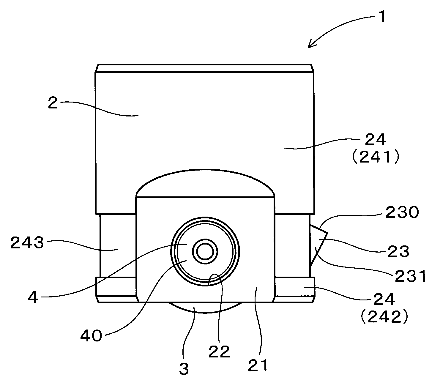
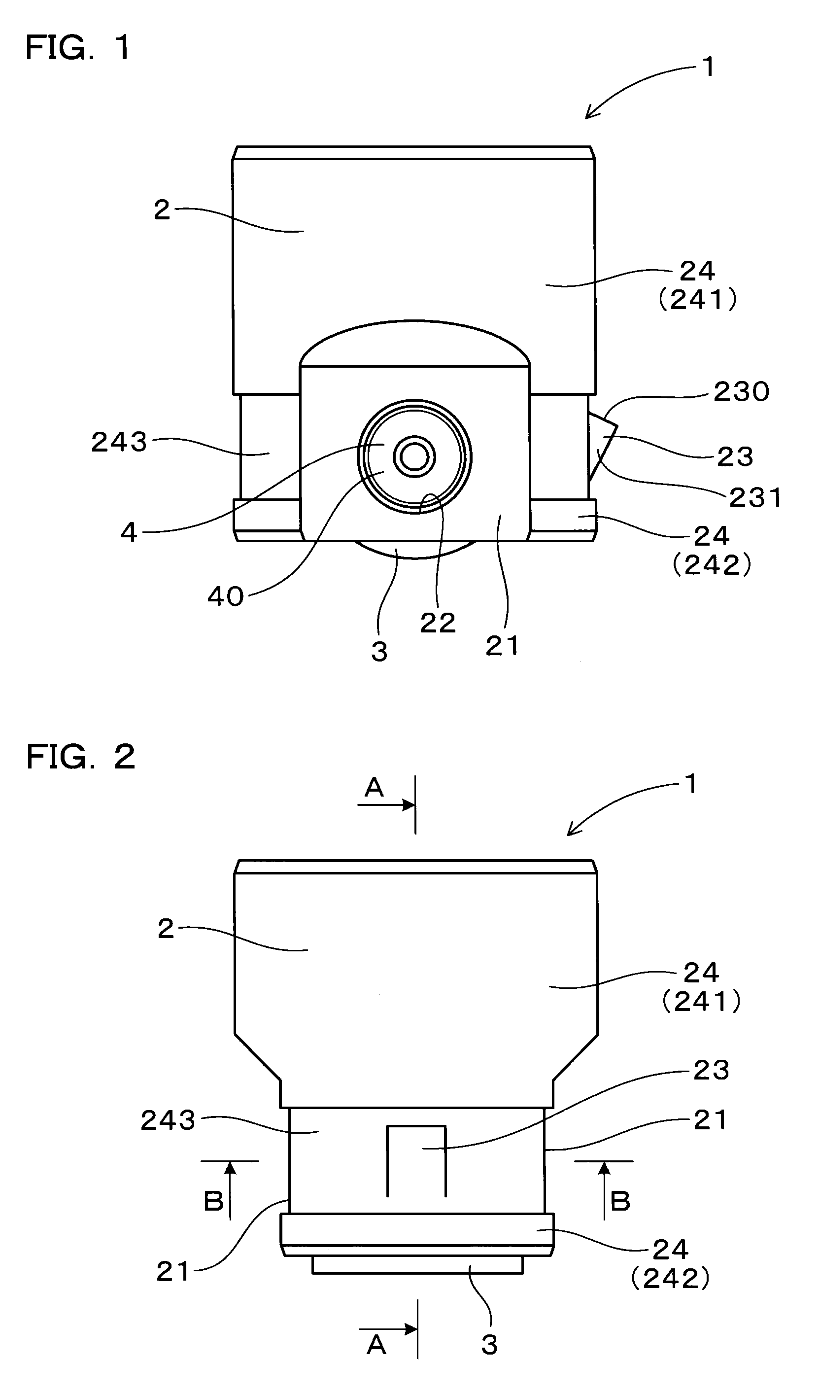
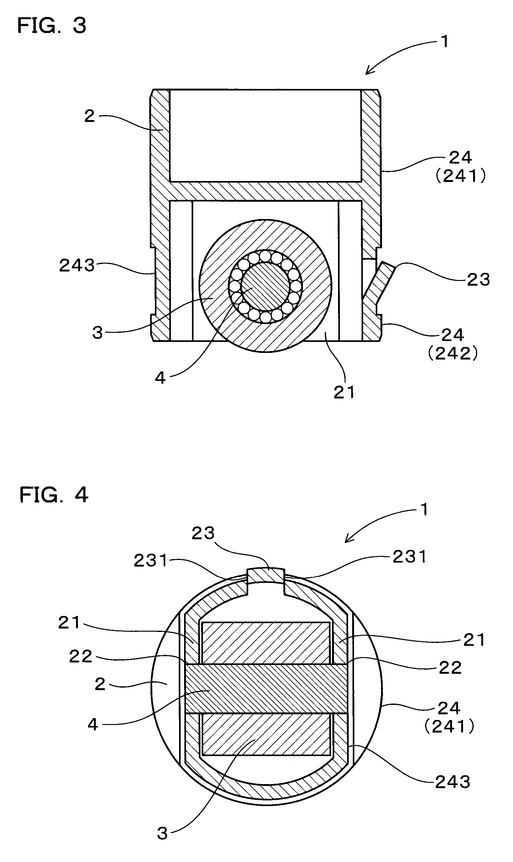
[0040]Specific embodiments of the roller lifter for internal combustion engines will be described below with reference to FIGS. 1 to 5.
[0041]The roller lifter 1 for internal combustion engines of this embodiment includes a cylindrical lifter body 2 having a sliding surface 24 on its outer circumferential surface that slides on an inner wall 51 of a cylinder 5, and a roller 3 rotatably attached to the lifter body 2 with an axial support pin 4 and making contact with a rotating cam lobe 6, as shown in FIGS. 1 and 5.
[0042]The lifter body 2 has a pair of support portions 21 for supporting the axial support pin 4.
[0043]Both ends 40 of the axial support pin 4 are inserted in support holes 22 formed in the pair of support portions 21 and mechanically fastened thereto.
[0044]The lifter body 2 has an anti-rotation retainer 23 extending radially outward from the sliding surface 24. The sliding surface 24 is formed both on the front and rear sides in the sliding direction of the anti-rotation r...
example 2
[0075]This embodiment is an example in which the roller lifter 1 is used as a valve lifter 70B in a valve gear 7B of a reciprocal engine.
[0076]The roller lifter 1 itself is configured the same as the roller lifter 1 of Embodiment 1.
[0077]The valve lifter 70B in the valve gear 7B is configured to slide inside a cylinder 5 arranged in a cylinder head 73 of the reciprocal engine, as the roller 3 is rotated by the rotating valve gear cam lobe 6 formed on a cam shaft 61 of the reciprocal engine, as shown in FIG. 6.
[0078]The valve lifter 70B abuts on a stem distal end 732 of a valve 730 in the reciprocal engine, and is arranged slidable up and down inside the cylinder 5 such as to open and close the valve 730 disposed to open and close an intake / exhaust port (intake port or exhaust port) 733.
[0079]An abutting portion 25 is configured to abut on the stem distal end 732 of the valve 730.
[0080]A retainer 77 is secured to the outer circumference of a stem part 731 of the valve 730. A spring 7...
example 3
[0082]As shown in FIGS. 7 to 9, this embodiment is an example of the roller lifter 1, in which one end in a direction orthogonal to the sliding direction of the anti-rotation retainer 23 is continuous with the small diameter part 243 while the other end extends radially outward from the sliding surface 24.
[0083]The roller lifter 1 of this embodiment has a pair of anti-rotation retainers 23. The respective ends of the anti-rotation retainers 23 that are continuous with the small diameter part 243 face each other, while the other ends (side end faces 231) are oriented to mutually opposite directions.
[0084]The side end faces 231 are formed such as to face the inner side face of the anti-rotation groove 53 (see FIG. 5) when the roller lifter 1 is mounted to the cylinder 5.
[0085]The rest is the same as Embodiment 1, with similar advantageous effects.
PUM
 Abstract
Description
Claims
Application Information
 - R&D
- Intellectual Property
- Life Sciences
- Materials
- Tech Scout
- Unparalleled Data Quality
- Higher Quality Content
- 60% Fewer Hallucinations
Browse by: Latest US Patents, China's latest patents, Technical Efficacy Thesaurus, Application Domain, Technology Topic, Popular Technical Reports.
© 2025 PatSnap. All rights reserved.Legal|Privacy policy|Modern Slavery Act Transparency Statement|Sitemap|About US| Contact US: help@patsnap.com


