Exhaust gas expansion tank and ozone generator system applying the same

a technology of exhaust gas expansion tank and ozone generator, which is applied in the direction of oxygen/ozone/oxide/hydroxide, functional valve types, transportation and packaging, etc., can solve the problems of increasing the operation steps, complicated system structure, and affecting the efficiency so as to simplify the operation procedure and reduce the pressure of the ozone generator. , the effect of increasing the pressure in the exhaust gas expansion tank

Active Publication Date: 2016-08-30
FUJIAN NEWLAND ENTECH CO LTD
View PDF3 Cites 0 Cited by
  • Summary
  • Abstract
  • Description
  • Claims
  • Application Information

AI Technical Summary

Benefits of technology

[0007]A first objective of the present invention is to provide an exhaust gas expansion tank which is simpler and more efficient.
[0010]A second objective of the present invention is to provide an ozone generator system which applying the exhaust gas expansion tank according to the first objective of the present invention, wherein said ozone generator system is capable of automatically adjusting the internal pressure in the system, is simple in structure and stable in operation.
[0014]The expansion tank and ozone generator system applying the same according to the present invention can bring about the following advantages:
[0017]3) Cooling water may be automatically supplemented into the ozone generator or surplus cooling water may be automatically evacuated into the exhaust gas expansion tank according to the amount of cooling water in the ozone generator. When the cooling water in the ozone generator increases in volume, surplus cooling water will flow into the exhaust gas expansion tank via the first water port. When the cooling water supplied into the exhaust gas expansion tank submerges the lower end port of the gas outlet conduit, the gas inside the tank body cannot be evacuated via the conduit, thus making the pressure in the exhaust gas expansion tank increase. Under these normal operation circumstances, water within the tank may submerge the lower end of the gas outlet conduit, thereby creating a water seal over the gas outlet conduit which prevents gas from being evacuated via the gas outlet conduit while still allowing water within the tank to automatically flow in / flow out of the tank through the first and / or second water port. When the cooling water in the ozone generator shrinks in volume, it is necessary to supplement cooling water, at this time, the pressure in the ozone generator is reduced, causing the pressure in the exhaust gas expansion tank to be higher than that in the ozone generator, thus the cooling water in the exhaust gas expansion tank automatically flows into the ozone generator under the effect of pressure, thereby achieving automatic supplementation of water to the ozone generator.
[0018]4) The cooling water in the ozone generator can be adjusted automatically and the gas exhaustion can be performed automatically, which simplifies the operation procedure and makes the system operation more stable.
[0019]5) No manual exhausting of gas is needed, which significantly reduces the workload during the installation, debugging and operation and meanwhile increases the security and stability of the system.

Problems solved by technology

Otherwise, the ozone will decompose during the generation thereof due to the high temperature, which affects the efficiency of the ozone generator.
This arrangement more or less addresses the pressure problem in the system, however, it makes the system structure complicated, increases operation steps and requires manual exhausting of gas to control the gas pressure in the expansion balls.
Thus the exhausting effect is manually affected and is not stable.
When frequent exhausting of gas is needed, it requires lots of manual work.
Moreover, in winter the cooling water shrinks in volume and no cooling water can be supplemented to the ozone generator.
In this case, it requires manually supplementing the cooling water and performing the exhausting of gas, which increases the workload and difficulty.

Method used


Image

  • Exhaust gas expansion tank and ozone generator system applying the same
  • Exhaust gas expansion tank and ozone generator system applying the same
  • Exhaust gas expansion tank and ozone generator system applying the same

Examples


embodiment 1

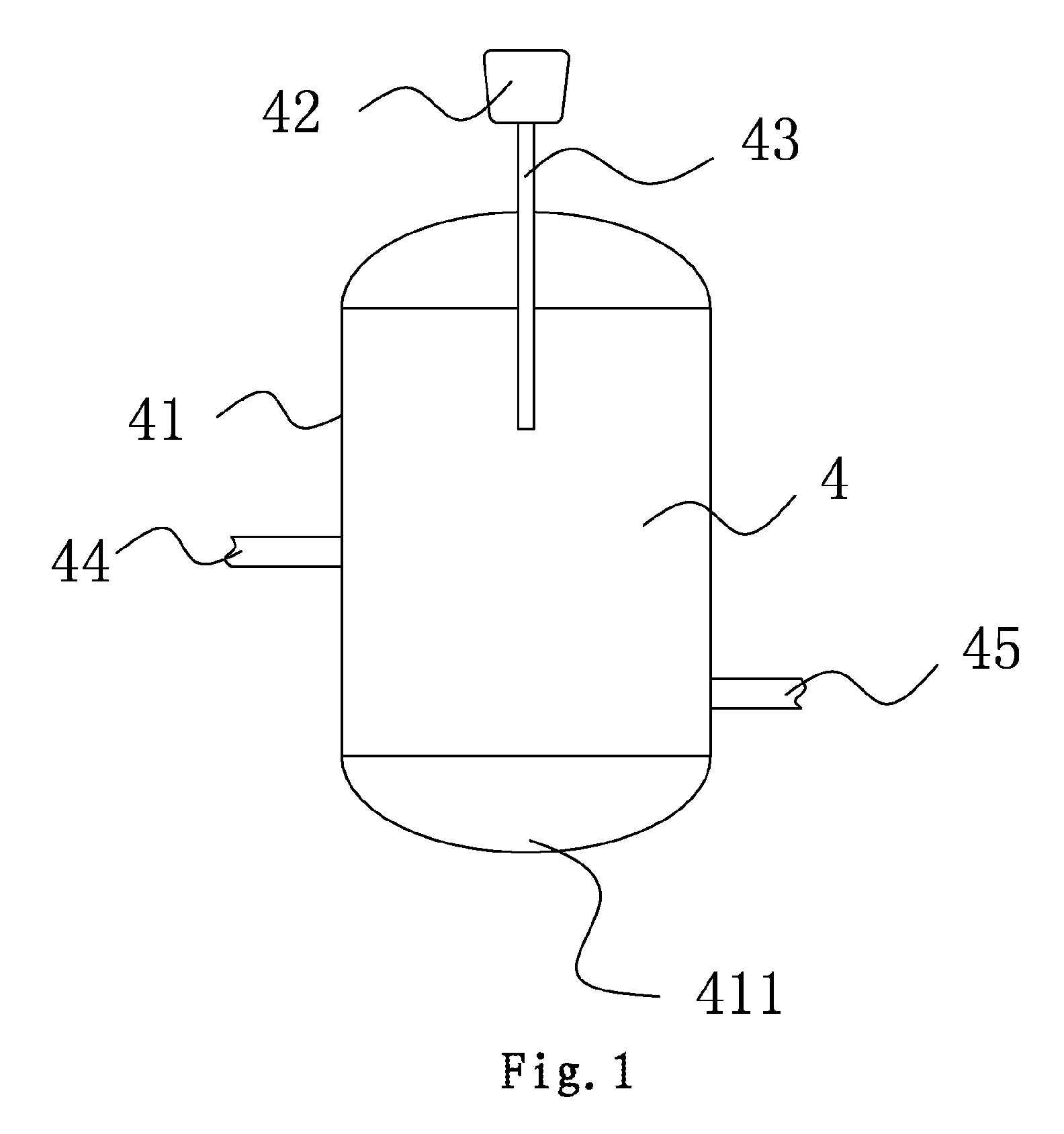
[0024]As shown in FIG. 1, an exhaust gas expansion tank 4 comprises a tank body 41 and an automatic exhaust valve 42, the exhaust gas expansion tank is provided at the top thereof with a gas outlet conduit 43, with the lower end of the gas outlet conduit extending into the tank body and being at a distance from the bottom 411 of the tank body. The automatic exhaust valve 42 is fixedly mounted on the upper end of the gas outlet conduit 43, and the tank body 41 is provided thereon with a first water port 44 and a second water port 45. When necessary, the tank body may be provided thereon with a supplementary water port.

embodiment 2

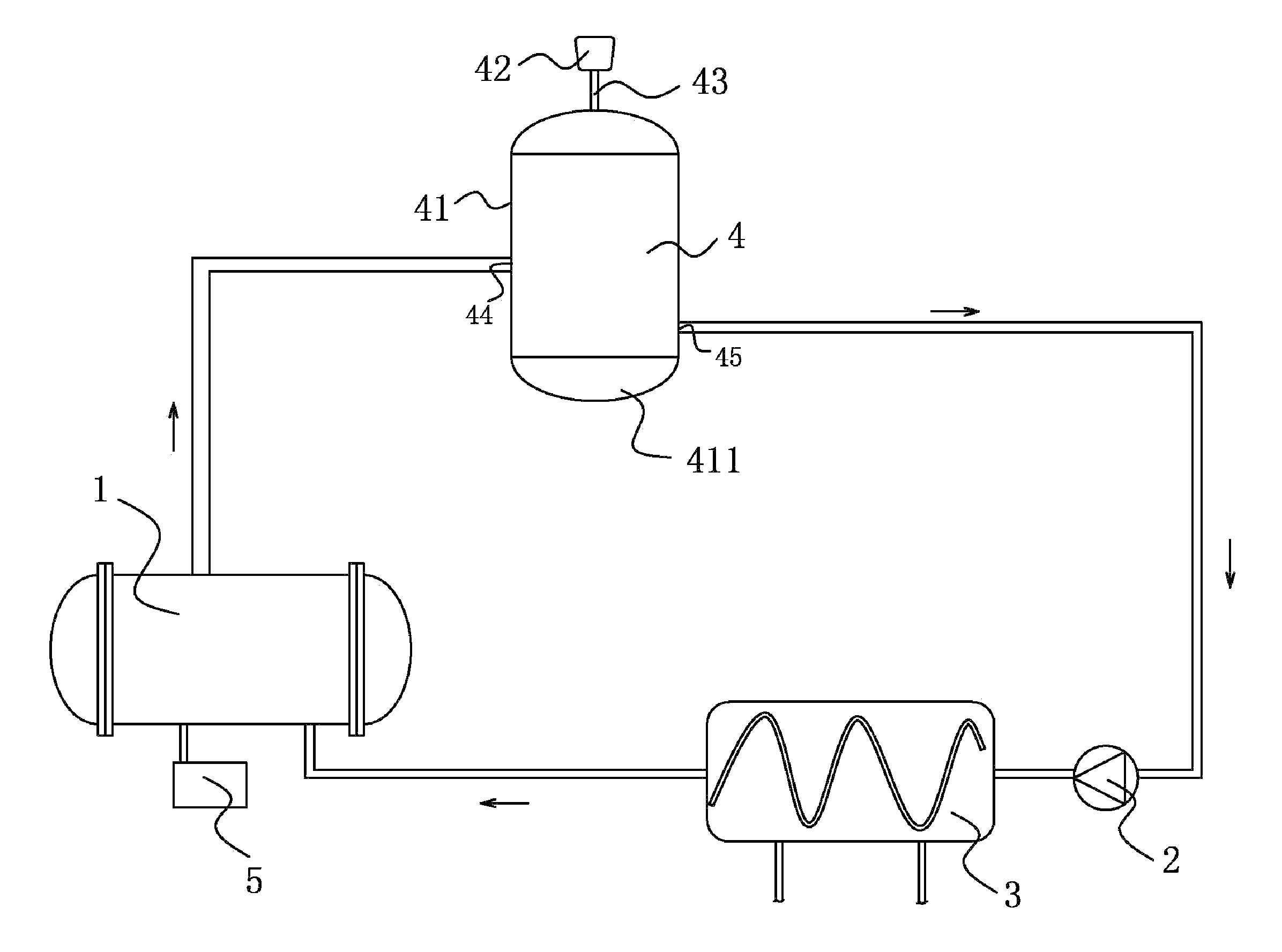
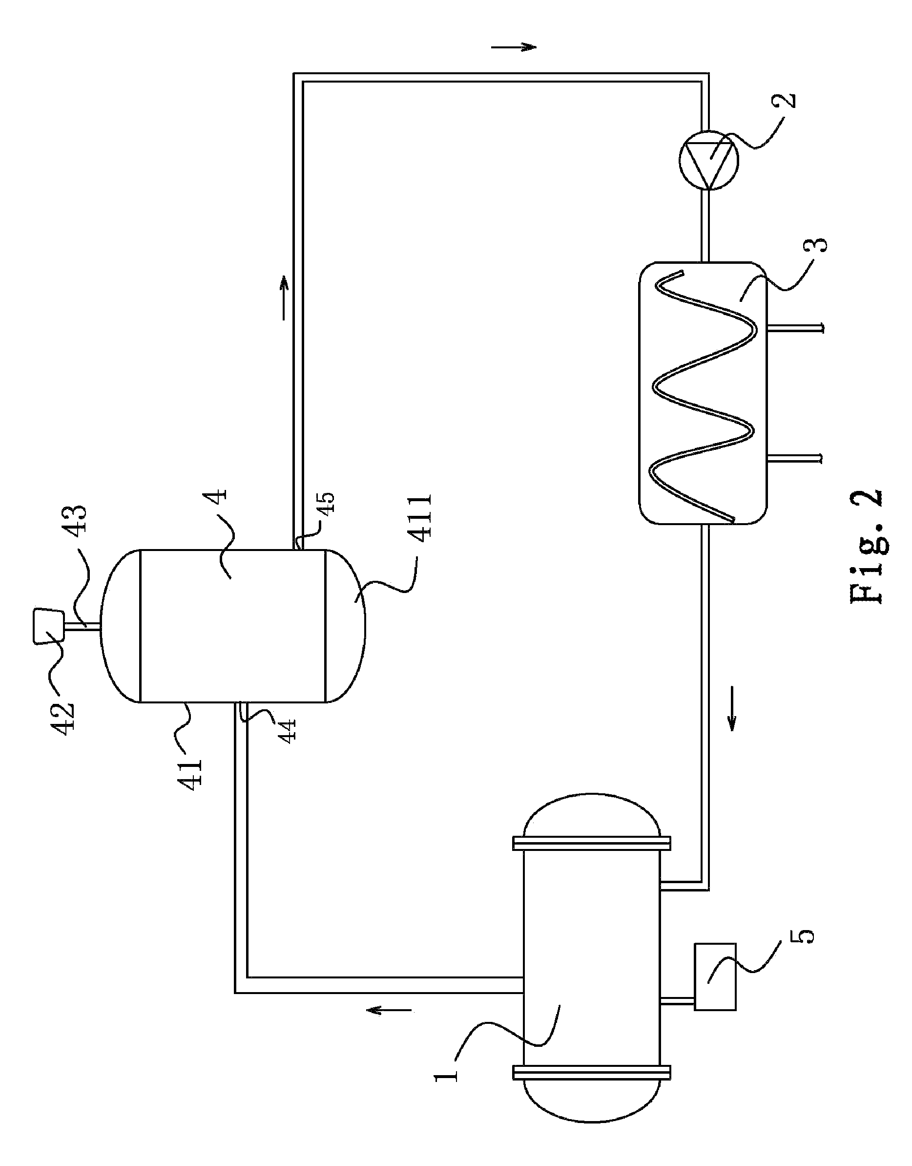
[0025]As shown in FIG. 2, an ozone generator system comprises an internal circulation loop consisting of an ozone generator 1, a circulation pump 2 and a plate heat exchanger 3, and further comprises an exhaust gas expansion tank 4 which is mounted between the ozone generator 1 and the circulation pump 2. The exhaust gas expansion tank 4 comprises a tank body 41 and an automatic exhaust valve 42, the exhaust gas expansion tank is provided at the top thereof with a gas outlet conduit 43, with the lower end of the gas outlet conduit 43 extending into the tank body and being at a distance from the bottom 411 of the tank body. The automatic exhaust valve 42 is fixedly mounted on the upper end of the gas outlet conduit 43, and the tank body is provided thereon with a first water port and a second water port, which are respectively communicated with the ozone generator and the circulation pump via a conduit. The internal circulation loop further comprises a supplementary water reservoir 5...


PUM

PropertyMeasurementUnit
distanceaaaaaaaaaa
thermal energyaaaaaaaaaa
temperatureaaaaaaaaaa

Abstract

The present invention relates to an exhaust gas expansion tank and an ozone generator system applying the same. The exhaust gas expansion tank includes a tank body and an automatic exhaust valve, and is provided at the top thereof with a gas outlet conduit, the lower end of the gas outlet conduit extending into the tank body and being at a distance from the bottom of the tank body, the automatic exhaust valve fixedly mounted on the upper end of the gas outlet conduit, and the tank body having a first water port and a second water port. The ozone generator system applying the exhaust gas expansion tank is simplified in system structure, can evacuate gas automatically and omit the manual exhausting of gas, thereby the operation procedure is simplified, the thermal expansion of the system is effectively controlled and the stability of the system operation is increased.

Description

CROSS-REFERENCE TO RELATED APPLICATIONS[0001]This application claims priority to Chinese Patent Application Nos. 201310024822.9 and 201320035431.2, both filed Jan. 24, 2013, the disclosures of which are hereby incorporated in their entirety by reference.BACKGROUND OF THE INVENTION[0002]1. Field of the Invention[0003]The present invention relates to the field of ozone generator system, in particular to an exhaust gas expansion tank and an ozone generator system applying the same.[0004]2. Description of Related Art[0005]The ozone used in industry is usually generated by large ozone generator, which releases a lot of thermal energy in operation, thus cooling procedure is necessary in the meantime. Otherwise, the ozone will decompose during the generation thereof due to the high temperature, which affects the efficiency of the ozone generator. Water cooling ozone generator is excellent in cooling effect, leads to no ozone loss and can continue working stably for a long time, therefore t...

Claims


Application Information

Patent Timeline
Patent Type & Authority Patents(United States)
IPC IPC(8): F16K24/04C01B13/10
CPCC01B13/10C01B2201/76Y10T137/3084
Inventor CHEN, JIANYANG, XIAOZHENYAO, XIANGYANGWANG, MEIYAN
Owner FUJIAN NEWLAND ENTECH CO LTD
Why Eureka
Try Eureka