Acoustic damping device for chambers with grazing flow

a technology of acoustic damping and chambers, which is applied in the direction of mechanical equipment, machines/engines, lighting and heating apparatus, etc., can solve the problems of disturbing the bias flow of gas through the neck and the mouth into the damping volume, and achieve the effect of effectively reducing the combustion dynamics and effective damping

Active Publication Date: 2016-08-30
ANSALDO ENERGIA SWITZERLAND AG
View PDF5 Cites 6 Cited by
  • Summary
  • Abstract
  • Description
  • Claims
  • Application Information

AI Technical Summary

Benefits of technology

[0012]It is an object of the invention, to provide an acoustic damper that is capable of damping effectively in a gas turbine under operation and therefore effectively reduces combustion dynamics ensued from operation of the gas turbine at certain frequencies.
[0015]By means of the claimed opening or a number of openings located adjacent to the mouth of a damper the grazing flow is deflected and therefore does not disturb the bias flow through the neck and the mouth of the damper and as a result the performance of the damper is improved.
[0016]In a preferred embodiment of the claimed invention the at least one opening for sealing gas is located upstream of the mouth so as to deflect the grazing gas flow away from the mouth of the damper. If this opening is located upstream of the mouth it most efficiently protects the mouth from the grazing gas flow.
[0017]To even more efficiently deflect the grazing flow away from the mouth of the damper it may be advantageous to provide two or more openings upstream of the mouth. In embodiments where the preferred direction of the grazing flow may change it is preferred if three, four or even more openings are located around the mouth of the damper so as to deflect the grazing flow independent from its actual direction of flow and to protect the mouth of the damper from the grazing flow.
[0018]To optimize the effect of the claimed openings adjacent to the mouth the openings for sealing gas may have a circular, elliptic or square cross section. Of course, the selection of a specific cross section of the openings may be based on the efficiency, i.e. an optimal deflection of the grazing gas flow and little sealing gas consumption. Reducing the flow of sealing gas raises the overall efficiency of a gas turbine, since supplying a sealing gas with a higher pressure than the pressure inside the chamber requires energy.

Problems solved by technology

This grazing flow has a main or preferred direction more or less perpendicular to the neck of the damper and therefore may disturb the bias flow of gas through the neck and the mouth into the damping volume.

Method used


Image

  • Acoustic damping device for chambers with grazing flow
  • Acoustic damping device for chambers with grazing flow
  • Acoustic damping device for chambers with grazing flow

Examples


first embodiment

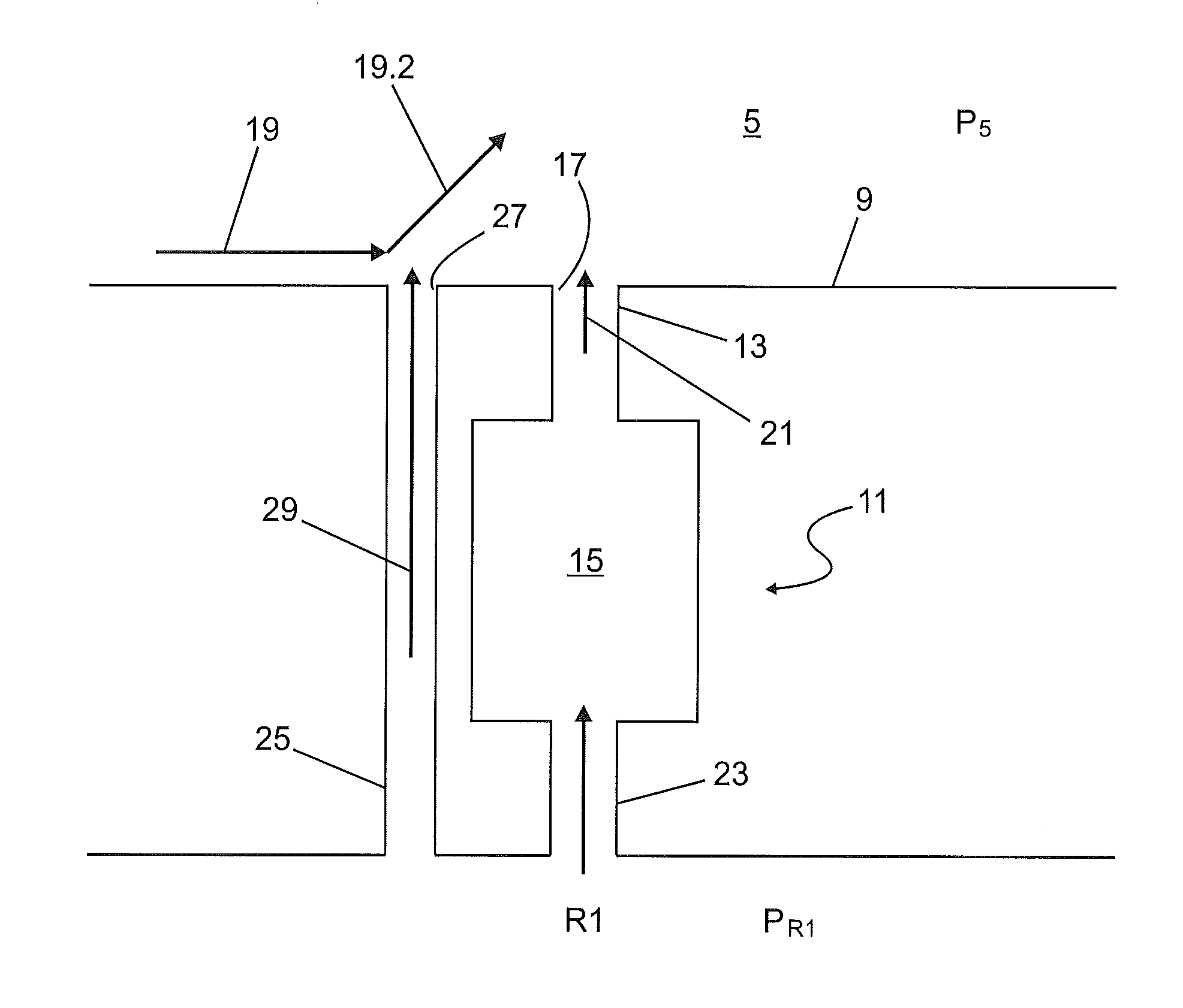
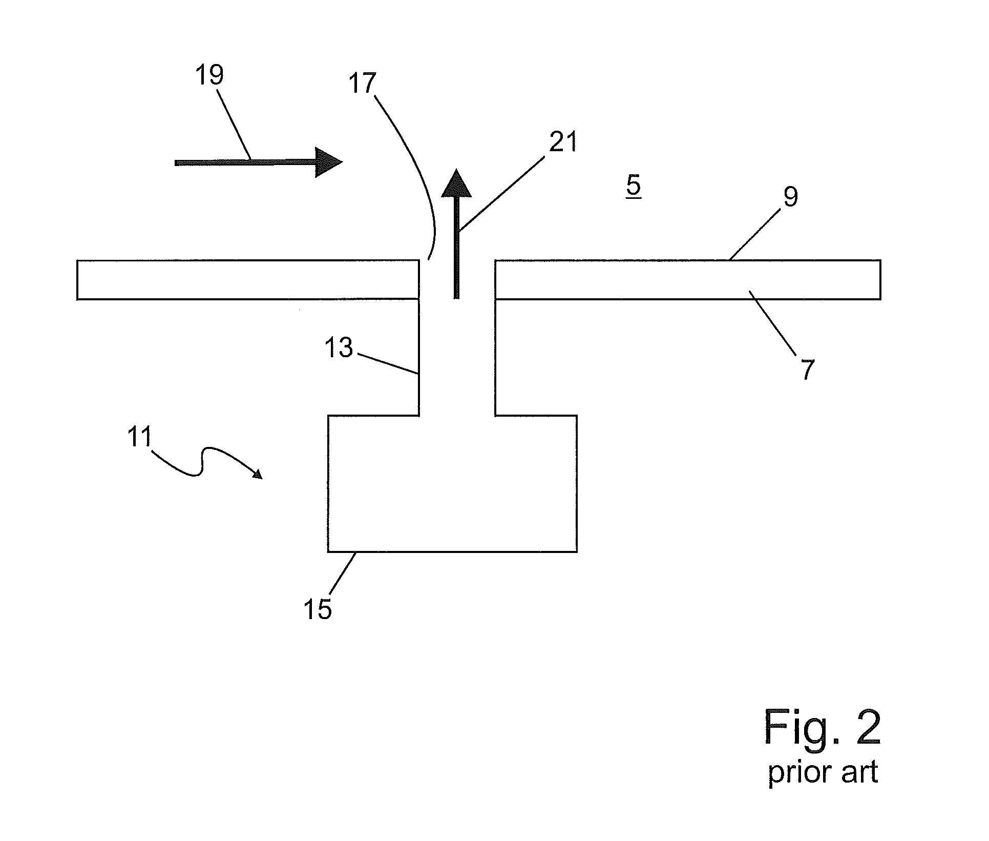
[0032]FIG. 3 illustrates the claimed invention. The reference numerals used are the same as in FIG. 2 and therefore only the differences are described in detail.

[0033]In FIG. 3 the bias flow has a preferred direction of flow from left to right and therefore upstream of the mouth 17 in FIG. 3 means on the left side of the mouth 17.

[0034]In this embodiment the damper 11 is a flow through damper which means that the damping volume 15 is connected via the neck 13 with the combustion chamber 5. At the opposite end of the damping volume 15 the damping volume 15 is connected via a small bore 23 to a further chamber R1.

[0035]As can be seen from FIG. 3, adjacent to the mouth 17 and upstream of the mouth 17 there is a further bore 25 with an opening 27. The bore 25 connects chambers 5 and R1.

[0036]Since the pressure pR1 in the chamber R1 is higher than the pressure p5 in the chamber 5 sealing air flows through the bore 25 and the opening 27 from chamber R1 into chamber 5. Since the bore 23 ha...

second embodiment

[0052]FIG. 5 illustrates the invention with two bore 25 and 32 adjacent to the mouth 17 of the damper 11. In this case, one opening 27 is upstream of the mouth 17 and a further opening 35 is downstream of the mouth 17. As can be seen from FIG. 6, the windshield 37 derived from the air or gas stream through the opening 35 supports and reinforces the windshield 31 starting from the first opening 27.

[0053]Therefore, the bias flow 21 through the mouth 17 is even better protected from the grazing flow.

[0054]In FIG. 7 several designs and arrangements of the bores that serve to supply sealing gas or air 29 for building up a windshield 31 are illustrated.

[0055]The embodiment 7a) has already been described in conjunction with FIG. 4.

[0056]In the embodiment illustrated in FIG. 7b) the opening 27 has an elliptic cross-section which broadens the windshield 31 and therefore results in a better protection of the bias flow 21.

[0057]In the embodiment illustrated in FIG. 7c) there are two openings 2...


PUM


Abstract

An acoustic damping device is provided which includes at least one opening for a sealing gas to deflect a grazing gas flow away from the mouth of an acoustic damper.

Description

CROSS-REFERENCE TO RELATED APPLICATIONS[0001]This application claims priority to EP application 14157239.6 filed Feb. 28, 2014, the contents of which are hereby incorporated in its entirety.TECHNICAL FIELD[0002]The invention relates to the acoustic damping of combustion dynamics. Combustion dynamics in the meaning of this application comprises pulsations, acoustic oscillations, pressure and velocity fluctuations and what is called in the everyday language “noise”.BACKGROUND OF INVENTION[0003]Combustion dynamics occur in combustors of gas turbines, for example, as a consequence of changes in the fuel supply. Excessive pressure fluctuations may result in damage of machine components. For reasons of simplification subsequently the term “chamber” is used and comprises all locations where combustion dynamics occur. In these chambers a gas (for example a mixture of fuel and air or a hot combustion gas) flows with a high velocity.[0004]To reduce these combustion dynamics it is well known i...

Claims


Application Information

Patent Timeline
Patent Type & Authority Patents(United States)
IPC IPC(8): F02C7/24F23R3/06F01D25/30
CPCF23R3/06F01D25/30F23R2900/00014F05D2220/32F05D2260/96F23M20/005F02C7/24F23R3/002
Inventor GENIN, FRANKLIN MARIETONON, DEVISBOTHIEN, MIRKO RUBENPENNELL, DOUGLAS ANTHONY
Owner ANSALDO ENERGIA SWITZERLAND AG
Why Eureka
Try Eureka