
Loudness level control for audio reception and decoding equipment

a technology of loudness level control and audio reception, applied in the direction of volume compression/expansion, instruments, sound input/output, etc., to achieve the effect of saving loudness levels, and ensuring the level of loudness

Active Publication Date: 2016-08-30
DISH TECH L L C
View PDF20 Cites 5 Cited by
  • Summary
  • Abstract
  • Description
  • Claims
  • Application Information

AI Technical Summary

Benefits of technology

The invention provides a computer method for adjusting the loudness levels of audio signals for playback on a connected audio playback device. This is done by detecting the playback of audio signals, recording them, and analyzing them to determine their loudness level. Based on this analysis, the method adjusts the loudness levels of the audio signals until they are as loud as each other. The adjusted loudness levels are then saved for future reproduction of the audio signals. The invention also provides an audio receiver device with control software for implementing this method. The technical effect of the invention is to ensure consistent loudness levels between different audio signals, making it easier for users to enjoy them.

Problems solved by technology

However, the proliferation of different available audio formats for digital encoding, audio equipment for decoding a received signal, and even standards and protocols for connecting different pieces of equipment together, means that there are a large number of audio pathways an audio signal can take before it is decoded and heard by a user.
This is undesirable as it means that the listener must frequently search for the remote control and readjust the volume to a comfortable level when changing channels or audio inputs.
The end listener is often not aware that the problem arises due to the complexity of the broadcast and programming chain and will believe that the loudness fault lies with the provider of the audio equipment, for example.

Method used


Image

  • Loudness level control for audio reception and decoding equipment
  • Loudness level control for audio reception and decoding equipment
  • Loudness level control for audio reception and decoding equipment

Examples


Embodiment Construction

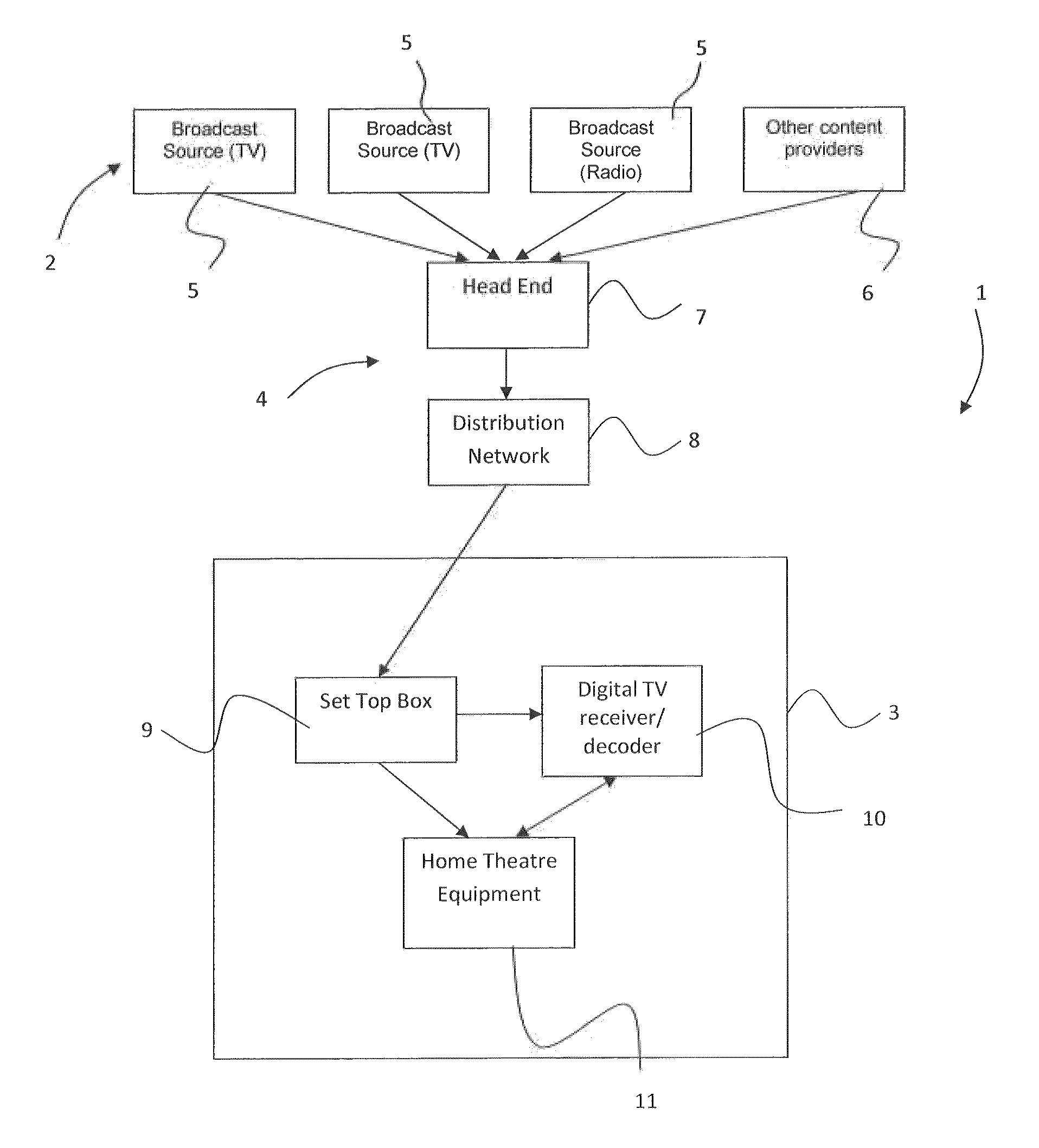
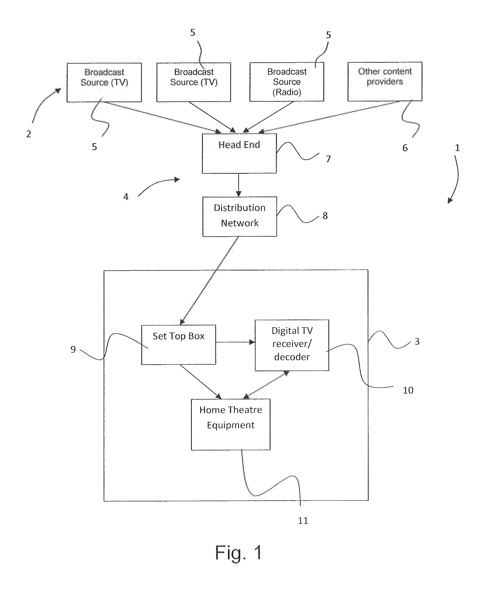
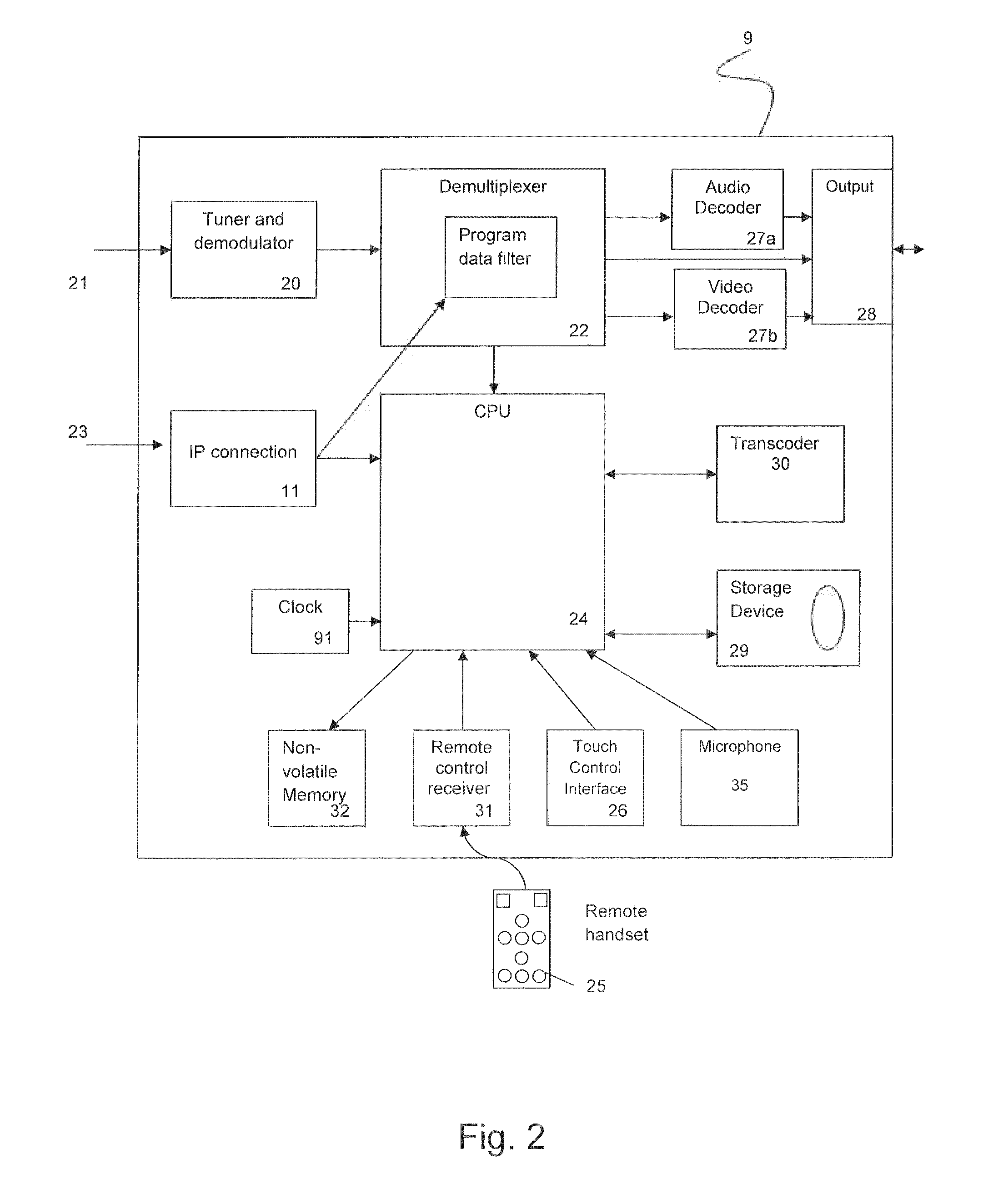
[0027]Embodiments of the invention will now be described. These relate to methods, apparatus, systems and computer programs for determining the gain (positive or negative) to be applied to a signal output from an audio receiver device, such as an integrated receiver / decoder (IRD) or set top box (STB), or integrated TV, so that on playback via a connected audio playback device, the audio decoded from different transports streams will appear to the listener to be equal in loudness.

[0028]In particular, examples of a computer implemented method and apparatus for performing audio equalisation in an audio receiver device connected to one or more audio playback devices, such as a television unit, computer screen and speakers, amplifier or home theatre equipment will be described. In the examples given, the method and apparatus use an equalisation process which compares audio signals received in different audio formats (e.g. MPEG-1 Layer II, AC-3 2.0, AC-3 5.1 and HE-AAC) with one another, ...


PUM


Abstract

The application discusses a computer implemented method and apparatus for performing audio equalization in an audio receiver device, such as an integrated receiver / decoder or set top box, or integrated TV, connected to one or more audio playback devices, such as a television unit, computer screen and speakers, amplifier or home theater equipment. The method and apparatus use an equalization process which compares audio signals received in different audio formats (e.g. MPEG-1 Layer II, AC-3 2.0, AC-3 5.1 and HE-AAC) with one another, allowing a correction gain factor to be determined for equalizing the perceived loudness of the signals when played-back at a connected playback device. The correction gain factor is then applied in the audio receiver device before output.

Description

PRIORITY CLAIM[0001]This application claims the benefit of and priority to European patent application entitled “LOUDNESS LEVEL CONTROL FOR AUDIO RECEPTION AND DECODING EQUIPMENT”, having application Ser. No. 13 / 178,947.1, filed Aug. 1, 2013, and which is incorporated herein by reference in its entirety.BACKGROUND[0002]The invention relates to audio reception and decoding equipment, and in particular to digital television or radio apparatus for use in the home, in which the loudness levels of audio signals received in different audio formats is equalised for user playback.[0003]Commercial and state owned broadcasting corporations have transmitted audio and video signals for entertainment and information purposes, since the early years of the twentieth century, using analogue encoding techniques, in which a property of the continuously varying electromagnetic wave was used to represent the audio or video information.[0004]In recent years, signals have become transmitted for the most ...

Claims


Application Information

Patent Timeline
Patent Type & Authority Patents(United States)
IPC IPC(8): H03G7/00H03G3/20G06F3/16H03G3/00H04R3/00H03G9/00H03G5/16H03G5/00
CPCG06F3/165H03G3/20H04R3/00H03G5/165H03G5/005H03G9/005H04R2430/01H04R2420/07H03G3/3005
Inventor ROBINSON, DAVID
Owner DISH TECH L L C
Learn More