Linear cutting stapler

a stapler and line cutting technology, applied in the field of medical instruments, can solve the problems of high cost, complicated structure, difficult manufacturing and assembly, etc., and achieve the effects of simple structure, good promotion value, and easy manufacturing

Active Publication Date: 2016-09-06
TOUCHSTONE INTERNATIONAL MEDICAL SCIENCE CO LTD
View PDF29 Cites 498 Cited by
  • Summary
  • Abstract
  • Description
  • Claims
  • Application Information

AI Technical Summary

Benefits of technology

[0008]An object of the present application is to provide a linear cutting stapler having a safety mechanism with simple structure.
[0010]A linear cutting stapler is provided, including an upper jaw and a lower jaw capable of being closed or opened relative to each other, a staple cartridge being provided at a distal end of the lower jaw. The lower jaw has a U shape provided slidably with a firing piece and a cutter pushing bar. The linear cutting stapler further includes a safety mechanism including a safety member and an opening. The opening is arranged on the firing piece and used to receive the safety member. Mounting or removing of the staple cartridge may drive the safety member to move in the direction perpendicular to the axis of the lower jaw, so as to enable the safety member to be disengaged from or engaged with the opening of the firing piece.
[0018]The present application has main beneficial effects such as a simple structure, easy to be manufactured, safe and reliable, as well as good promotion value.

Problems solved by technology

This may cause serious consequence as arising from only cutting without stapling.
All of the above structures are complicated, and difficult to be manufactured and assembled, as well as costly.

Method used


Image

  • Linear cutting stapler
  • Linear cutting stapler
  • Linear cutting stapler

Examples


Embodiment Construction

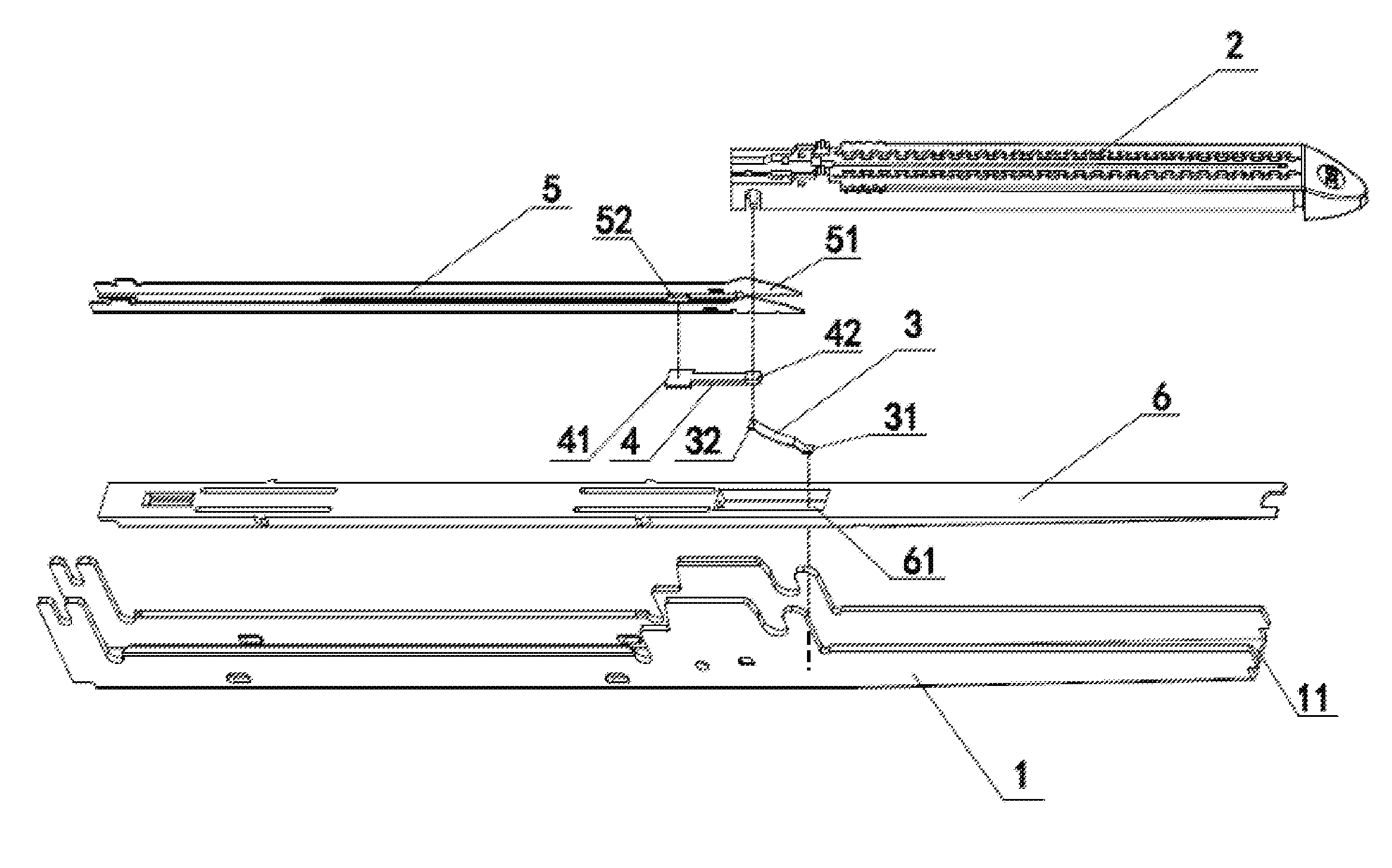
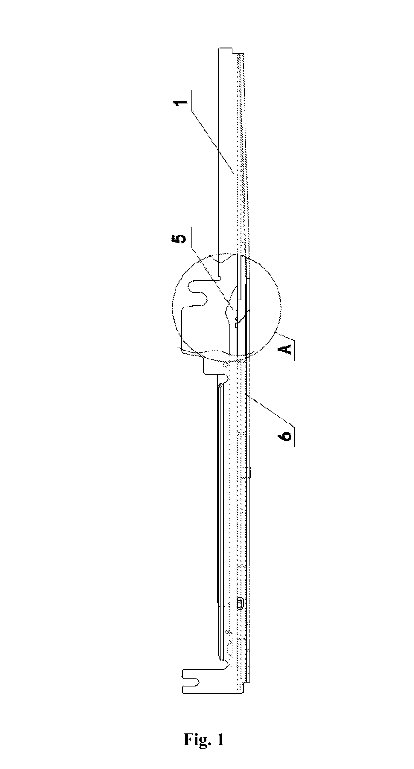
[0026]As shown in FIGS. 1 to 3, the present application provides a safety mechanism for a linear cutting stapler. Similar to the prior art, the linear cutting stapler includes a plastic shell, and an upper jaw and a lower jaw capable of being closed or opened relative to each other. A staple anvil (not shown) is provided at a distal end of the upper jaw, and a staple cartridge 2 is provided at a distal end of the lower jaw 1. Of course, the positions of the upper jaw and the lower jaw may be interchanged, and such a definition in the present application is only for the purpose of clarity.

[0027]The lower jaw 1 is in a U shape. A firing piece 5 and a cutter pushing bar (not shown) respectively for firing the staple pusher and cutting a tissue are slidably provided at a distal end of the lower jaw 1. In use, the tissue is placed between the staple anvil and the staple cartridge; then, the upper and lower jaws are moved towards each other to close the handle so as to enable the upper an...


PUM

PropertyMeasurementUnit
elastic forceaaaaaaaaaa
U shapeaaaaaaaaaa
movementaaaaaaaaaa

Abstract

A linear cutting stapler comprises: an upper jaw and a lower jaw (1) capable of closing or opening relative to each other. A staple cartridge (2) is disposed at a distal end of the lower jaw (1). The lower jaw (1) has a U shape, in which a striker (5) and a pushing rod are slidably disposed. The linear cutting stapler further comprises a safety mechanism. The safety mechanism comprises a safety piece (4), and an opening (52) opened on the striker (5) and for receiving the safety piece. The installation or removal of the staple cartridge (2) may drive the safety piece (4) to move in a direction perpendicular to the axis of the lower jaw (1), so that the safety piece (4) is disengaged from or engaged with the opening (52) of the striker (5). The linear cutting stapler has a simple structure, can be easily fabricated, and is safe and reliable.

Description

[0001]The present application claims the benefit of priority to Chinese Patent Application No. 201010581557.0 titled “LINEAR CUTTING STAPLER” and filed with the State Intellectual Property Office on Dec. 10, 2010, the entire disclosure of which is incorporated herein by reference.FIELD OF THE INVENTION[0002]The present application relates to a linear cutting stapler, which belongs to the technical field of medical instruments.BACKGROUND OF THE INVENTION[0003]Linear cutting staplers are widely used in surgical operations for wound closure, and internal tissue closure and excision. A typical linear cutting stapler as disclosed in U.S. Pat. No. 5,129,570 performs two functions of stapling and cutting, to remove the redundant tissue while stapling the wound. This kind of linear cutting stapler generally includes two jaws (i.e., an upper jaw and a lower jaw), a closing handle for closing the upper jaw and the lower jaw, a staple anvil and a staple cartridge arranged opposite to each othe...

Claims


Application Information

Patent Timeline
Patent Type & Authority Patents(United States)
IPC IPC(8): A61B17/068A61B17/072A61B17/32
CPCA61B17/068A61B17/0682A61B17/07207A61B2017/07271A61B2017/07278A61B2017/07285A61B2017/320052
Inventor CHEN, WANGDONGSHU, TUOPEI, YONGWANG
Owner TOUCHSTONE INTERNATIONAL MEDICAL SCIENCE CO LTD
Why Eureka
Try Eureka