Display apparatus

a technology of display apparatus and display screen, which is applied in the direction of lighting and heating apparatus, instruments, fibre light guides, etc., can solve the problems of reducing luminance, difficult to express gradation, and difficulty in gradation printing, so as to achieve the effect of reducing luminan

Active Publication Date: 2016-09-06
DENSO CORP +1
View PDF11 Cites 0 Cited by
  • Summary
  • Abstract
  • Description
  • Claims
  • Application Information

AI Technical Summary

Benefits of technology

[0007]It is an object of the present disclosure to provide a display apparatus that permits a light luminous region to change gradation of light and shade in a smooth or continuous expression.
[0009]Under such a configuration, the thickness of the attenuation portion formed in between the light input face and the light output face is provided to change as continuously increasing or becoming larger from a central portion to each of both end portions of the belt-like shape in the extended direction. This permits the function of attenuating the light transmitting from the light input face to the light output face to demonstrate more effectively or strongly as going to each of both the end portions of the light output face. The above configuration thus enables the light quantity of the output light outputted from the light output face to decrease smoothly or continuously from the central portion to the end portion in the extended direction. Therefore, the light luminous region provided by the light output face can appear with the gradation which decreases luminance smoothly from the central portion to each of both the end portions.

Problems solved by technology

The Inventors however found it difficult for the gradation with printing to provide a smooth or continuous change in luminance of the light luminous region for the following reason.
Thus, the printing seems to be difficult to express the gradation which decreases luminance smoothly or continuously in the light luminous region.

Method used


Image

  • Display apparatus
  • Display apparatus
  • Display apparatus

Examples


Embodiment Construction

[0017]The following describes an embodiment of the present disclosure with reference to drawings.

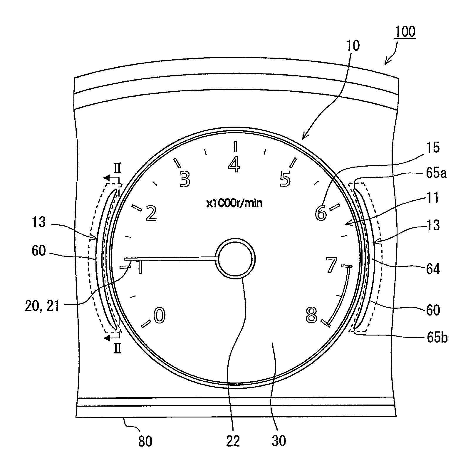
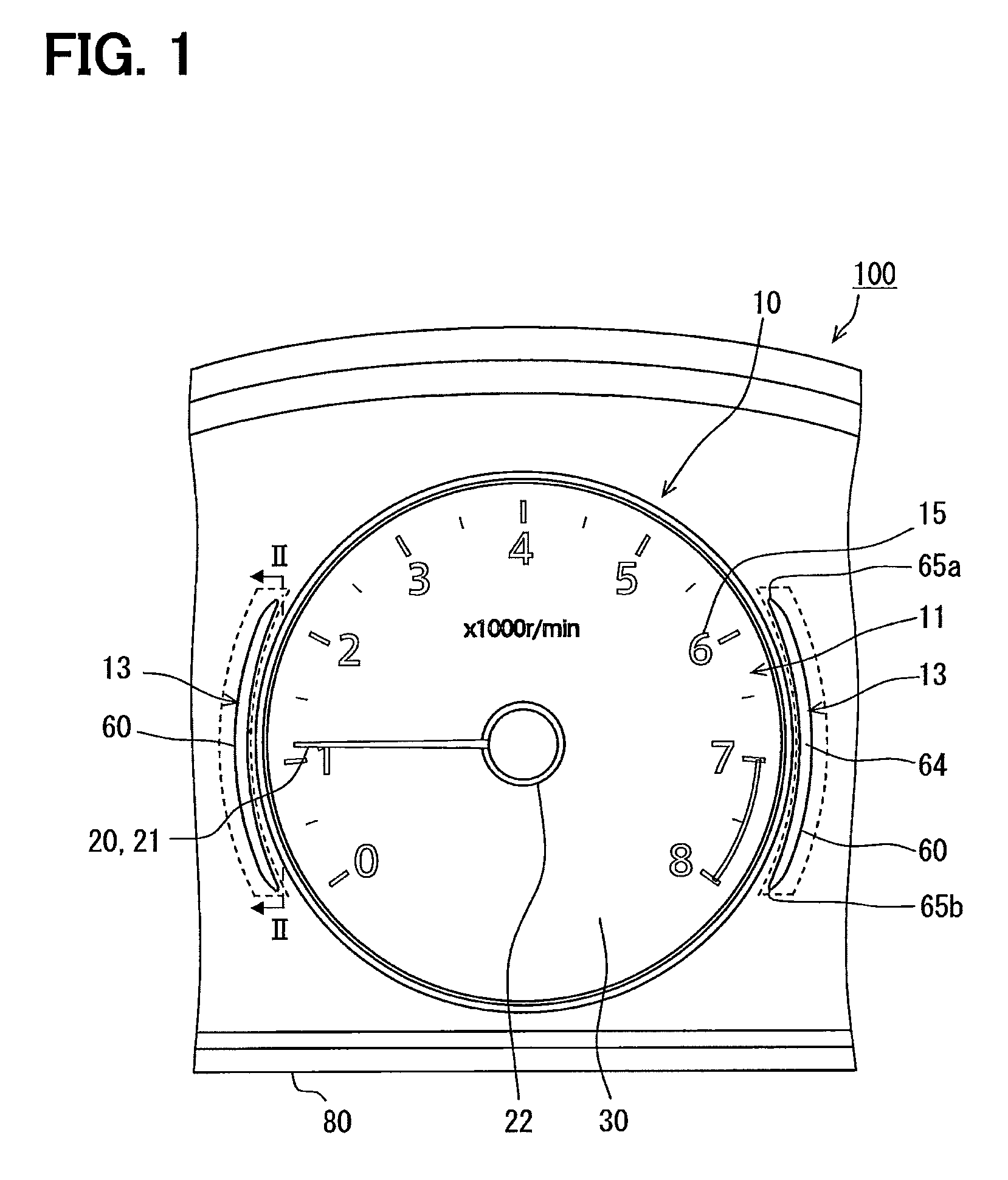
[0018]A combination meter 100 according to an embodiment of the present disclosure is contained in an instrument panel in a vehicle compartment of a subject vehicle such that the front side illustrated in FIG. 1 faces a driver's seat of the subject vehicle. The combination meter 100 is a vehicular display apparatus which displays a variety of information about the subject vehicle. The combination meter 100 includes several meters such as a tachometer 10 and other meters (unshown) of a speedometer, a water thermometer, a fuel gauge, and the like.

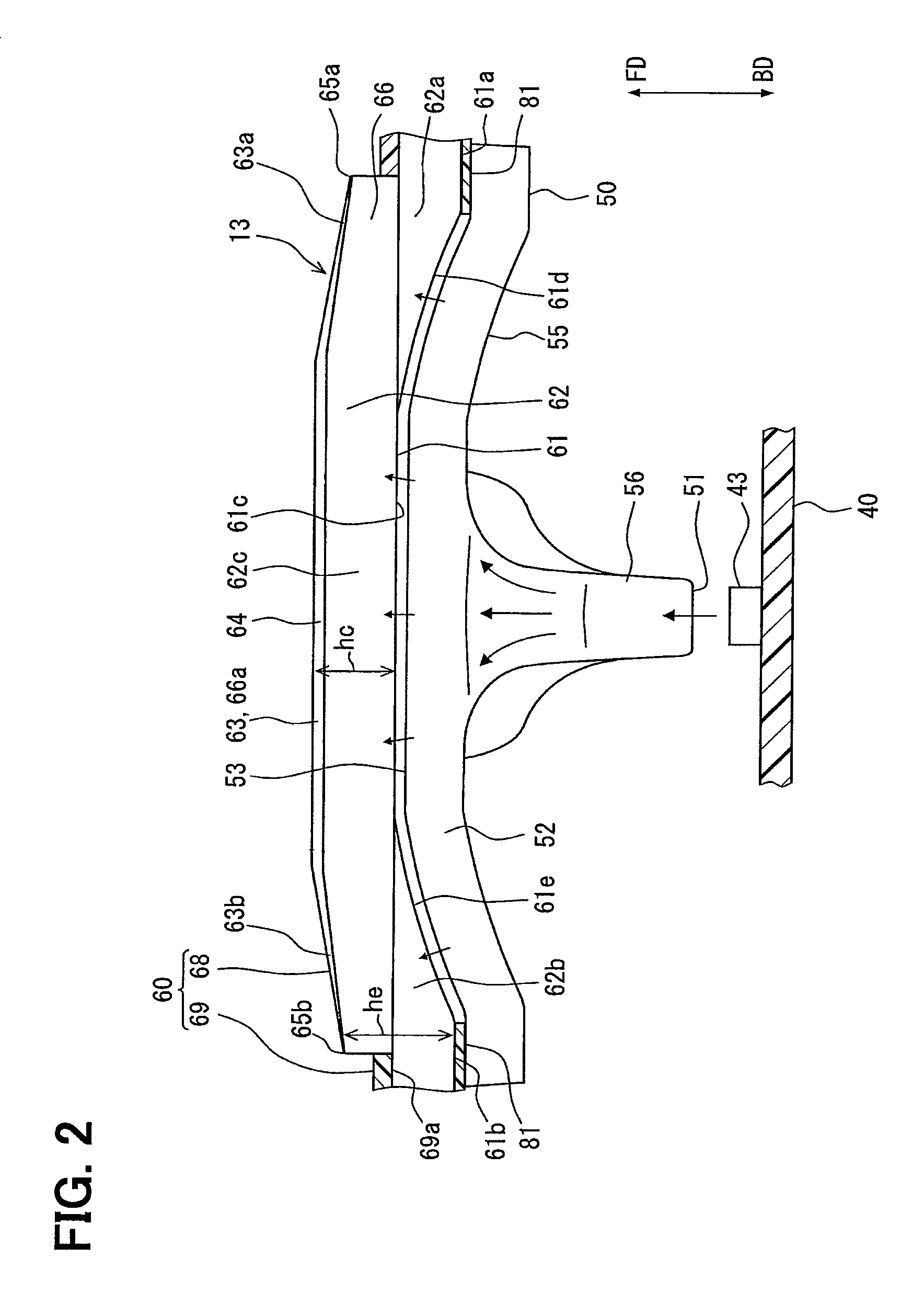
[0019]The tachometer 10 displays the information of rotation speed of an output axis of an internal-combustion engine mounted in the subject vehicle on a display region 11. The display of the tachometer 10 is configured by a combination of (i) the display region 11 and (ii) a peripheral light luminous region 13, which is arranged to be adjacent to...


PUM


Abstract

A display apparatus provides a display region to display information, and a peripheral light luminous region to output light. The display apparatus includes an indicator light source and a coloring transmissive member made of light transmissive material. The coloring transmissive member includes a light input face where the light emitted from the indicator light source enters; a light output face with a belt-like shape in an extended direction to form the light luminous region by outputting light inputted from the light input face; and an attenuation portion attenuating light transmitting from the light input face to the light output face. The attenuation portion has a thickness between the light input face and the light output face. The thickness changes to increase in the extended direction of the light output face as going from a central portion towards each of both end portions.

Description

CROSS REFERENCE TO RELATED APPLICATION[0001]The present application is based on Japanese Patent Application No. 2013-103187 filed on May 15, 2013, the disclosure of which is incorporated herein by reference.TECHNICAL FIELD[0002]The present disclosure relates to a display apparatus to display information.BACKGROUND ART[0003][Patent Literature 1] JP 2006-047271 A[0004]For instance, Patent Literature 1 describes an instrument panel provided with a liquid crystal display apparatus to display information. The liquid crystal display apparatus can be recognized by a viewer through an opening portion made of light transmissive texture provided in a meter dial plate. The opening portion in the meter dial plate has a peripheral edge provided with a gradation layer with printing or transfer.[0005]The Inventors examined the use of such gradation with printing described in Patent Literature 1 to a design in a display apparatus. That is, the gradation with printing is applied to a light output fa...

Claims


Application Information

Patent Timeline
Patent Type & Authority Patents(United States)
IPC IPC(8): B60Q1/00F21V33/00F21V8/00G01D11/28
CPCF21V33/0052G01D11/28G02B6/001G02B6/0046G02B6/0076G02B6/0001
Inventor KOBAYASHI, YASUHIROKUNO, MASAHIROKAMON, SHINJI
Owner DENSO CORP
Why Eureka
Try Eureka