Optical information reproduction device, optical information reproduction method, and information recording medium

a technology of optical information and reproduction method, which is applied in the field of optical information reproduction device, optical information reproduction method, and information recording medium, can solve the problems of difficult size (recording mark length) of recording mark that can be reproduced, and difficulty in achieving further increase in density, so as to achieve satisfactory reproduction of information and improve the modulation degree of reproduction signal

Inactive Publication Date: 2014-09-16
PANASONIC CORP
View PDF18 Cites 0 Cited by
  • Summary
  • Abstract
  • Description
  • Claims
  • Application Information

AI Technical Summary

Benefits of technology

[0012]The present invention has been devised in order to solve the problems and it is an object of the present invention to provide an optical information reproduction device, an optical information reproduction method, and an information recording medium capable of satisfactorily reproducing information even if the size of a recording region in which the information is recorded is smaller than a diffraction limit of light.
[0015]According to the present invention, even if the size of the recording region is smaller than the diffraction limit of light, it is possible to satisfactorily reproduce the information by making use of the fact that a plasmon resonance degree between the recording region and the resonance section of the plasmon resonance element changes according to a state of the recording region, whereby a reflected light amount or a transmitted light amount from the plasmon resonance element changes.
[0016]Since the size of the plasmon resonance element is not subjected to a spatial limitation, it is possible to form the plasmon resonance element larger than the recording region. Further, the reflected light or the transmitted light from the plasmon resonance element is detected by directly irradiating the reproduction light on the plasmon resonance element rather than near-field light. Therefore, it is possible to set the reflected light amount, the transmitted light amount, a light amount change of the reflected light amount, or a light amount change of the transmitted light amount sufficiently large. It is possible to improve a modulation degree of a reproduction signal.

Problems solved by technology

However, in the optical memory system in the past, there is a problem in that the size (recording mark length) of a recording mark that can be reproduced is limited by an optical limit size called diffraction limit determined by an NA (numerical aperture) of the objective lens and the wavelength of reproduction light and a further increase in density is difficult.
However, as a result of examination, the inventors have found a problem in the optical recording and reproduction device described in Patent Literature 1 in that, although high-density recording can be performed by forming a recording mark having size close to the size of the near-field light (e.g., about several ten nanometers), it is difficult to satisfactorily reproduce a recording mark having the size of the near-field light.
As a result, there is a problem in that a change in the intensity of scattered light detected according to presence or absence of the recording mark is, for example, smaller than 0.00001% with respect to the reproduction light amount and reproduction of information is difficult because the change in the intensity of the scattered light is too small.

Method used


Image

  • Optical information reproduction device, optical information reproduction method, and information recording medium
  • Optical information reproduction device, optical information reproduction method, and information recording medium
  • Optical information reproduction device, optical information reproduction method, and information recording medium

Examples


first embodiment

[0029]First, an optical information reproduction device, an optical information reproduction method, and an information recording medium in a first embodiment of the present invention are explained in detail with reference to FIGS. 1, 2, 3A, and 3B.

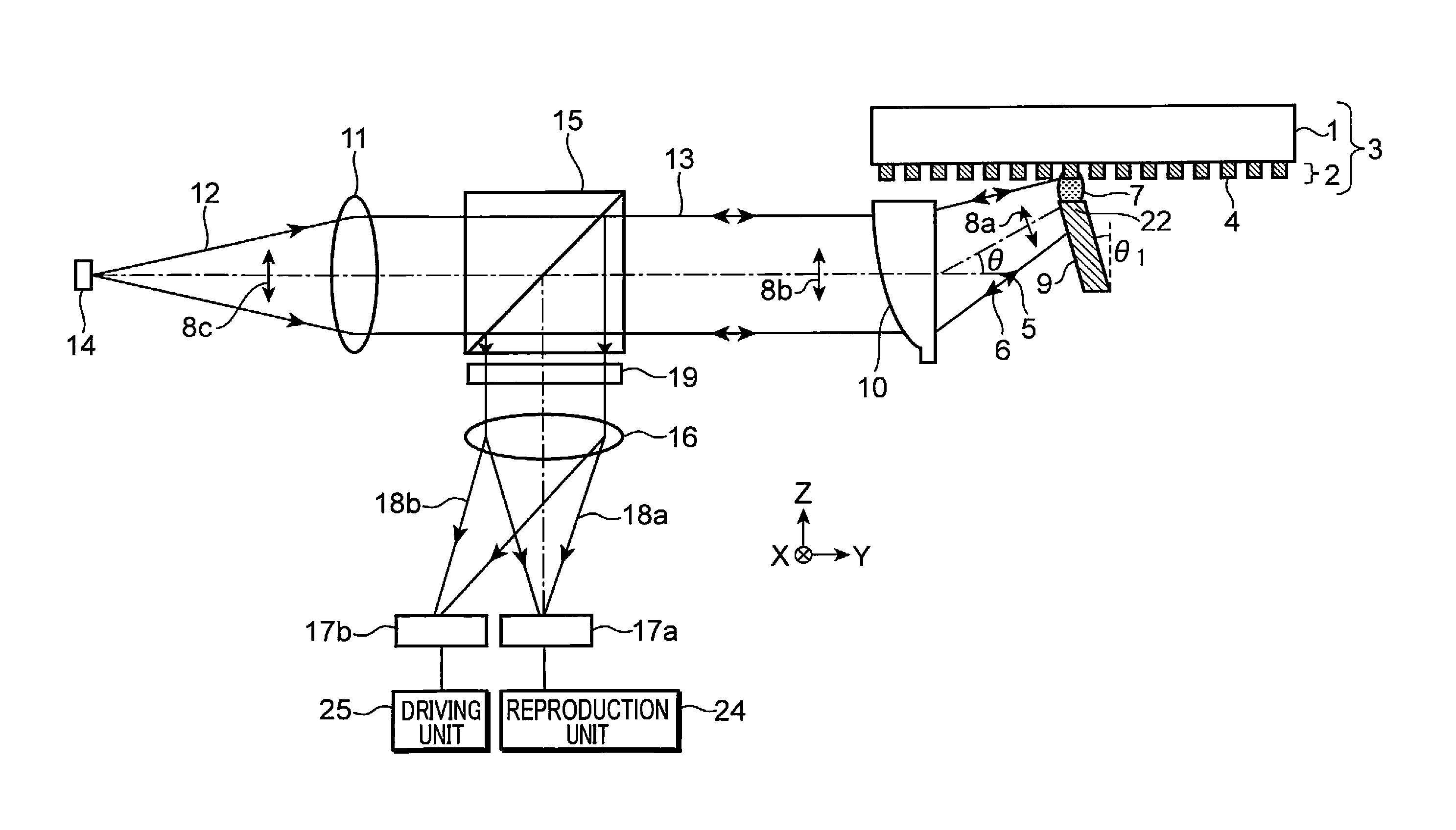
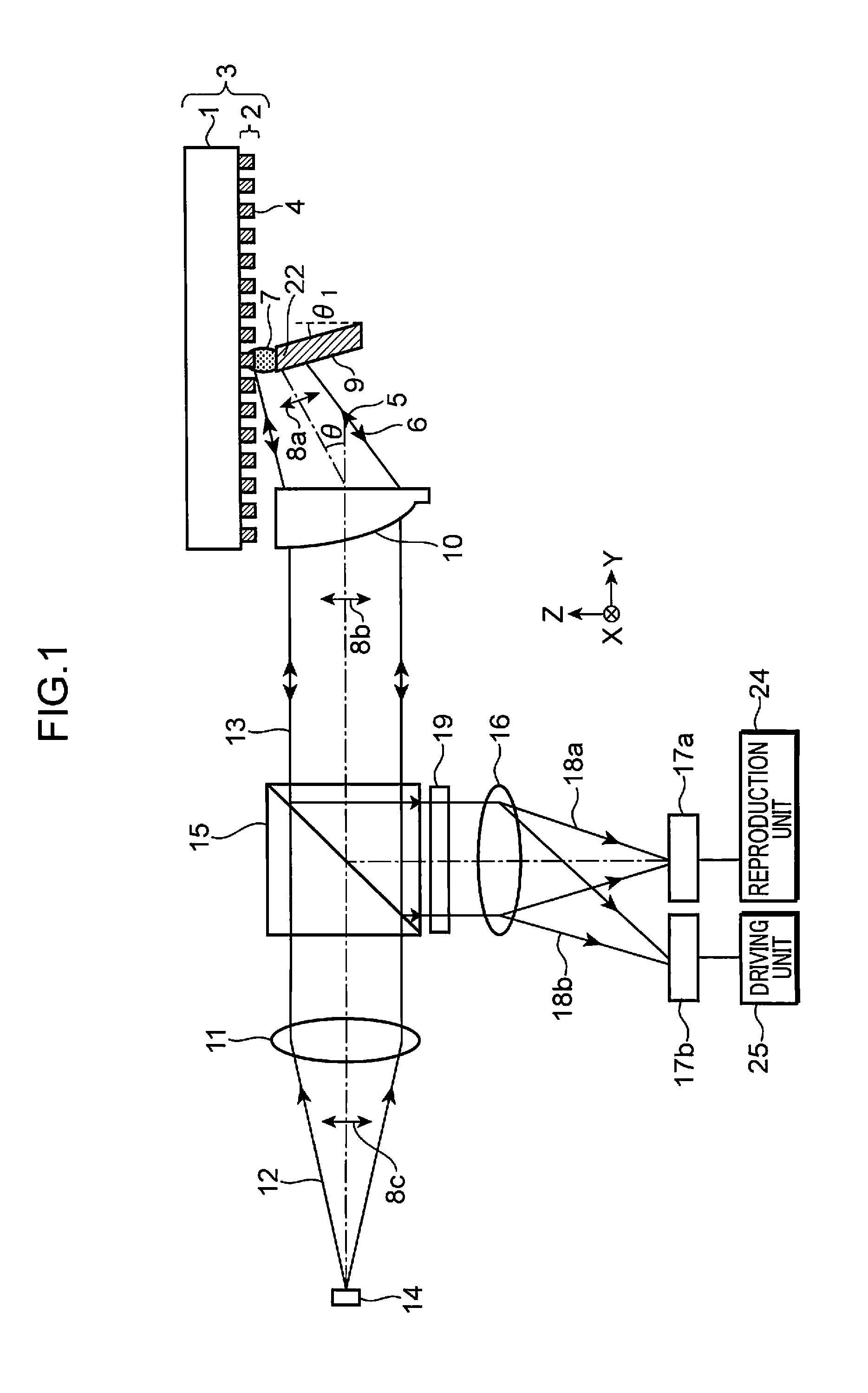
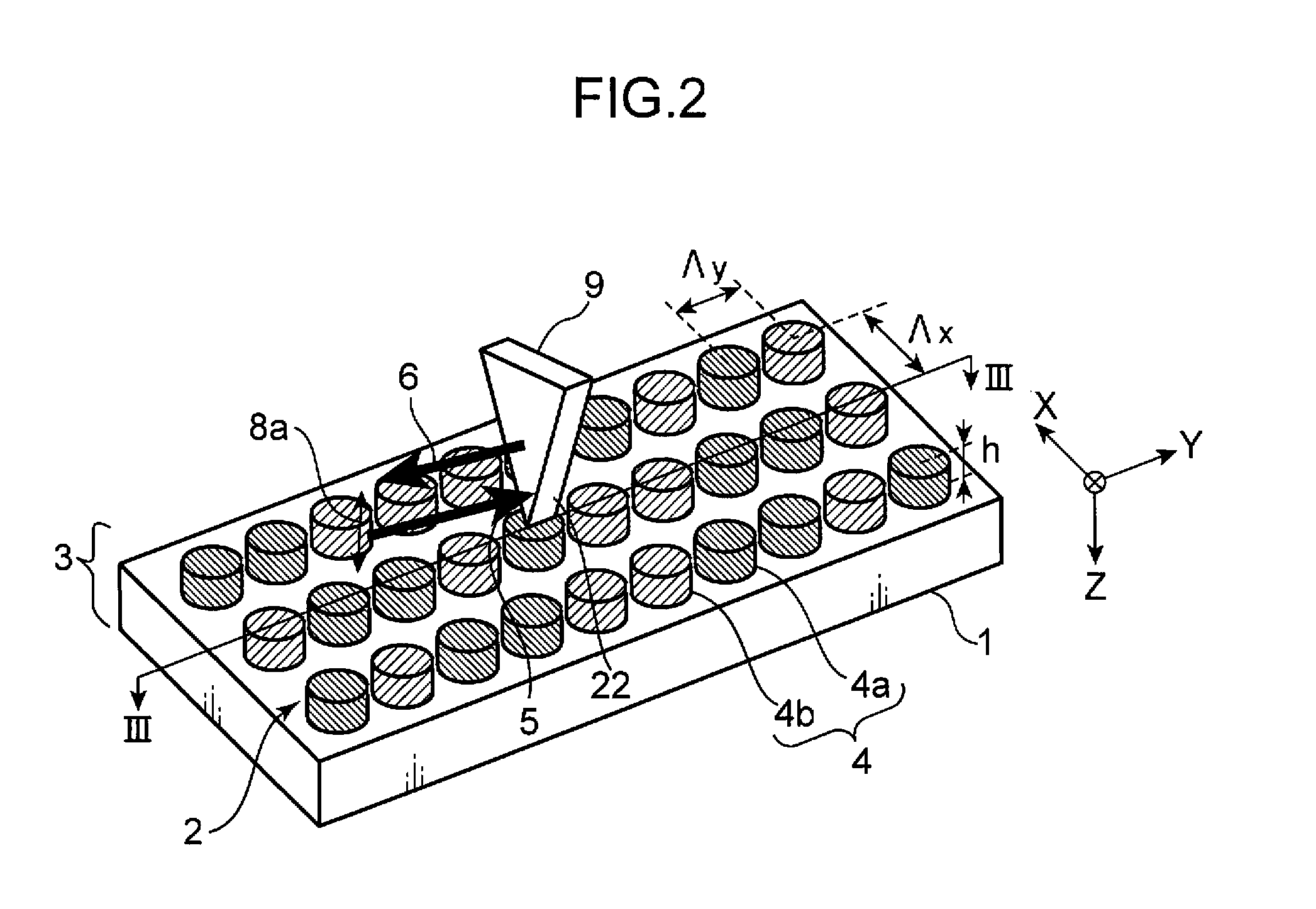
[0030]FIG. 1 is a diagram showing the configuration of an optical information reproduction device in a first embodiment of the present invention. FIG. 2 is an explanatory diagram showing a plasmon resonance element of the optical information reproduction device in the first embodiment of the present invention and a state in which information is reproduced from an information recording medium. FIG. 3A is a sectional view taken along line III-III in FIG. 2 showing a state of the vicinity of the plasmon resonance element in the case in which, in the first embodiment of the present invention, a recording region of the information recording medium is in a recorded state and a plasmon resonance degree is large. FIG. 3B is a sectional view taken...

second embodiment

[0088]An information recording medium in a second embodiment of the present invention is explained next. FIG. 5 is a sectional view showing the configuration of an information recording medium 3c in the second embodiment of the present invention. The information recording medium 3c is different from the information recording medium 3 in the first embodiment in that a protective layer 23, of which dielectric constant has a real part with a positive sign, is formed in an upper layer of the recording region 4 of the recording layer 2 formed on the substrate 1. In other words, the information recording medium 3c further includes, in the upper layer of the recording region 4, the protective layer 23 of which dielectric constant has a real part with a positive sign and which is used for protecting the recording region 4. Since the protective layer 23 is provided, it is possible to improve resistance to environment of the particle functioning as the recording region 4 formed of the recordi...

third embodiment

[0092]An optical information reproduction device in a third embodiment of the present invention is explained centering on differences from the optical information reproduction device in the first embodiment with reference to FIGS. 6, 7, 8A, and 8B.

[0093]FIG. 6 is a diagram showing the configuration of the optical information reproduction device in the third embodiment of the present invention. FIG. 7 is an explanatory diagram showing a plasmon resonance element of the optical information reproduction device in the third embodiment of the present invention and a state in which information is reproduced from an information recording medium. FIG. 8A is a sectional view taken along line VIII-VIII in FIG. 7 showing a state of the vicinity of the plasmon resonance element in the case in which, in the third embodiment of the present invention, a recording region of the information recording medium is in a recorded state and a plasmon resonance degree is large. FIG. 8B is a sectional view t...


PUM

PropertyMeasurementUnit
wavelengthaaaaaaaaaa
sizeaaaaaaaaaa
sizeaaaaaaaaaa

Abstract

An optical information reproduction device includes a light source (14) configured to emit reproduction light, a plasmon resonance element (9) including a resonance section (22) arranged adjacent to a recording region (4) of a recording layer (2), the resonance section (22) causing plasmon resonance between the recording region (4) and the resonance section (22), a photodetector (17a) configured to detect reflected light or transmitted light from the plasmon resonance element (9) on which the reproduction light is irradiated, and a reproduction unit (24) configured to determine, on the basis of a detection signal from the photodetector (17a), whether the recording region (4) is in a recorded state or an unrecorded state, and reproduce information recorded in the recording region (4).

Description

TECHNICAL FIELD[0001]The present invention relates to an optical information reproduction device and an optical information reproduction method for optically reproducing information recorded on an information recording medium, and also relates to an information recording medium including at least a substrate and a recording layer.BACKGROUND ART[0002]As an optical information reproduction device, an optical memory system has been put to practical use in which an optical disk such as a CD (compact disc), a DVD, or a BD (Blu-Ray disc), an optical card, or the like is used as an information recording medium.[0003]A reproduction principle of a conventional optical memory system is shown in FIG. 10 in a simplified form. FIG. 10 is an explanatory diagram showing a part of the configuration of a conventional optical information recording and reproduction device and a state in which information is reproduced from an information recording medium.[0004]In the conventional optical information r...

Claims


Application Information

Patent Timeline
Patent Type & Authority Patents(United States)
IPC IPC(8): G11B7/00G11B7/24B82Y20/00B82Y30/00G11B7/005G11B7/1387G11B7/2531G11B7/2532G11B7/2533G11B7/2538
CPCG11B7/1387B82Y30/00B82Y20/00G11B7/005G11B7/2538G11B7/2532G11B7/2533G11B7/2531
Inventor SHIONO, TERUHIROKOBAYASHI, YOSHIHARU
Owner PANASONIC CORP
Why Eureka
Try Eureka