
Reproducing apparatus and reproducing method

a technology of reproducing apparatus and reproducing method, which is applied in the direction of optical recording/reproducing/erasing methods, instruments, and record information storage, etc., can solve the problems of signal light intensity decline and signal reading error, and achieve high responsiveness

Active Publication Date: 2019-07-02
SONY CORP
View PDF19 Cites 0 Cited by
  • Summary
  • Abstract
  • Description
  • Claims
  • Application Information

AI Technical Summary

Benefits of technology

This approach enables accurate and stable reproduction of land / groove recording type optical media by effectively reducing noise interference and enhancing signal responsiveness, leading to improved signal-to-noise ratios and long-term stability.

Problems solved by technology

For example, when reproducing a multilayered optical disc, the signal light intensity decreases, and there is a high possibility that an error occurs in signal reading.

Method used


Image

  • Reproducing apparatus and reproducing method
  • Reproducing apparatus and reproducing method
  • Reproducing apparatus and reproducing method

Examples


Embodiment Construction

[0048]The embodiments described below are specific favorable examples of the present technology and a variety of technologically preferable limitations is given thereto. However, the scope of the present technology is not limited to these embodiments unless, in particular, the description that limits the present technology is described in the following description.

[0049]Note that the description of the present technology is done in the following order.

[0050]

[0051]

[0052]

[0053]

[0054]

1. Conventional Homodyne Detection Method

[0055]Prior to the description of the reproducing method of one embodiment of the present technology, a conventional homodyne detection method and an improved homodyne detection method will be described. Hereinafter, as an example, a homodyne detection method based on a so-called phase diversity method will be described.

[0056]“Optical Recording Medium to be Reproduced”

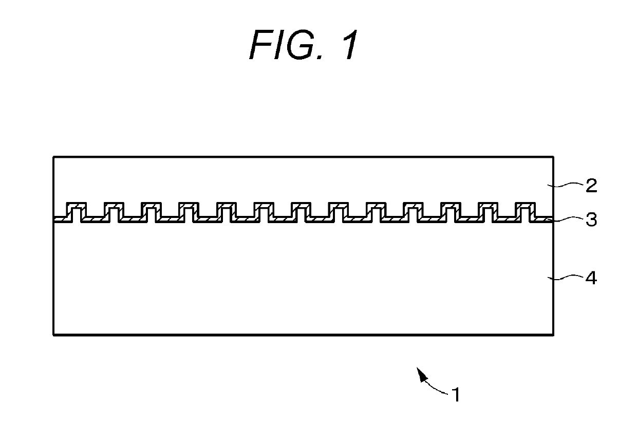
[0057]FIG. 1 illustrates a cross-sectional structural view of an optical recording medium 1 to be r...


PUM

PropertyMeasurementUnit
refractive indexaaaaaaaaaa
wavelengthaaaaaaaaaa
phase differenceaaaaaaaaaa

Abstract

Provided is a reproducing apparatus including: a reproduction signal generating circuit that calculates a first difference signal which is a difference between a first light receiving signal obtained by the first light receiving element and a second light receiving signal obtained by the second light receiving element, and a second difference signal which is a difference between a third light receiving signal obtained by the third light receiving element and a fourth light receiving signal obtained by the fourth light receiving element, and uses the first difference signal, the second difference signal, a phase difference between a crosstalk component and an average phase of the signal light beam, and an optical path length difference between the signal light beam and the reference light beam to obtain a reproduction signal; and a phase extraction circuit that obtains a successive change amount and updates with a successive variation.

Description

CROSS REFERENCE TO PRIOR APPLICATION[0001]This application is a National Stage Patent Application of PCT International Patent Application No. PCT / JP2017 / 002958 (filed on Jan. 27, 2017) under 35 U.S.C. § 371, which claims priority to Japanese Patent Application No. 2016-090125 (filed on Apr. 28, 2016), which are all hereby incorporated by reference in their entirety.TECHNICAL FIELD[0002]The present technology relates to a reproducing apparatus and a reproducing method applied to reproduce an optical medium such as an optical disk.BACKGROUND ART[0003]For example, when reproducing a multilayered optical disc, the signal light intensity decreases, and there is a high possibility that an error occurs in signal reading. In order to solve this problem, a homodyne detection method of amplifying a detection signal by using light interference is known (see Patent Document 1).[0004]In Patent Document 1, as a homodyne system for detecting a light beam in which a signal light beam and a referenc...

Claims


Application Information

Patent Timeline
Patent Type & Authority Patents(United States)
IPC IPC(8): G11B7/135G11B7/007G11B7/005G11B20/10
CPCG11B7/0053G11B7/005G11B20/10009G11B7/135G11B7/00718G11B7/13G11B7/1395
Inventor SAITO, KIMIHIROHORIGOME, TOSHIHIROSEKIGUCHI, KOJIKUROKAWA, KOTARO
Owner SONY CORP
Learn More