
X-ray generation module, X-ray imaging apparatus, and X-ray imaging method

a technology of x-ray generation and x-ray image, which is applied in the field of x-ray generation module, x-ray imaging apparatus, and x-ray imaging method, can solve the problems of blurred 2d image, difficulty in distinguishing mass from other tissues in the acquired 2d x-ray image,

Inactive Publication Date: 2016-09-13
SAMSUNG ELECTRONICS CO LTD
View PDF10 Cites 5 Cited by
  • Summary
  • Abstract
  • Description
  • Claims
  • Application Information

AI Technical Summary

Benefits of technology

[0014]It is an aspect of the exemplary embodiments to provide a plurality of X-ray generation modules that are movable independently of one another, and an X-ray imaging apparatus and an X-ray imaging method using the X-ray generation modules, which may acquire 2D and 3D X-ray images free from blurring due to movement of the X-ray generation modules.

Problems solved by technology

The mammography system may be advantageous to detect breast diseases at low cost, but has difficulty in distinguishing mass from other tissues in the acquired 2D X-ray image.
In particular, upon image capture of a dense breast, an inspector (e.g., a medical professional) of the acquired 2D X-ray image is limited in his or her ability to distinguish diseases from internal tissues of the breast using only the acquired 2D X-ray image because the tissues overlap one another.
However, the step-and-shot method may cause shaking of the X-ray generator due to a damping motion of the X-ray generator that becomes heavy when the X-ray generator stops at the respective image-capture positions during X-ray emission, resulting in a blurred 2D image.
The continuous-scan method also causes a blurred 2D image due to movement of the X-ray generator as the X-ray generator emits X-rays while moving.
Thus, although the tomosynthesis system easily detects diseases as compared to the mammography system, the tomosynthesis system may require a plurality of X-ray emissions, which causes a problem in regard to patient radiation exposure.

Method used


Image

  • X-ray generation module, X-ray imaging apparatus, and X-ray imaging method
  • X-ray generation module, X-ray imaging apparatus, and X-ray imaging method
  • X-ray generation module, X-ray imaging apparatus, and X-ray imaging method

Examples


Embodiment Construction

[0053]Reference will now be made in detail to the exemplary embodiments of the present disclosure, examples of which are illustrated in the accompanying drawings, wherein like reference numerals refer to like elements throughout.

[0054]Hereinafter, exemplary embodiments of an X-ray generation module, an X-ray imaging apparatus, and an X-ray imaging method will be described in detail. In the following description, the X-ray imaging apparatus will be exemplary described as a tomosynthesis system, although it is understood that the X-ray imaging apparatus is not limited to being implemented as a tomosynthesis system.

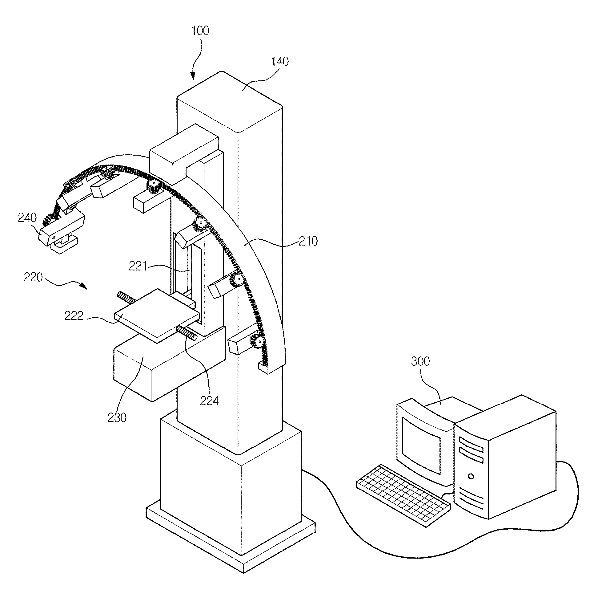
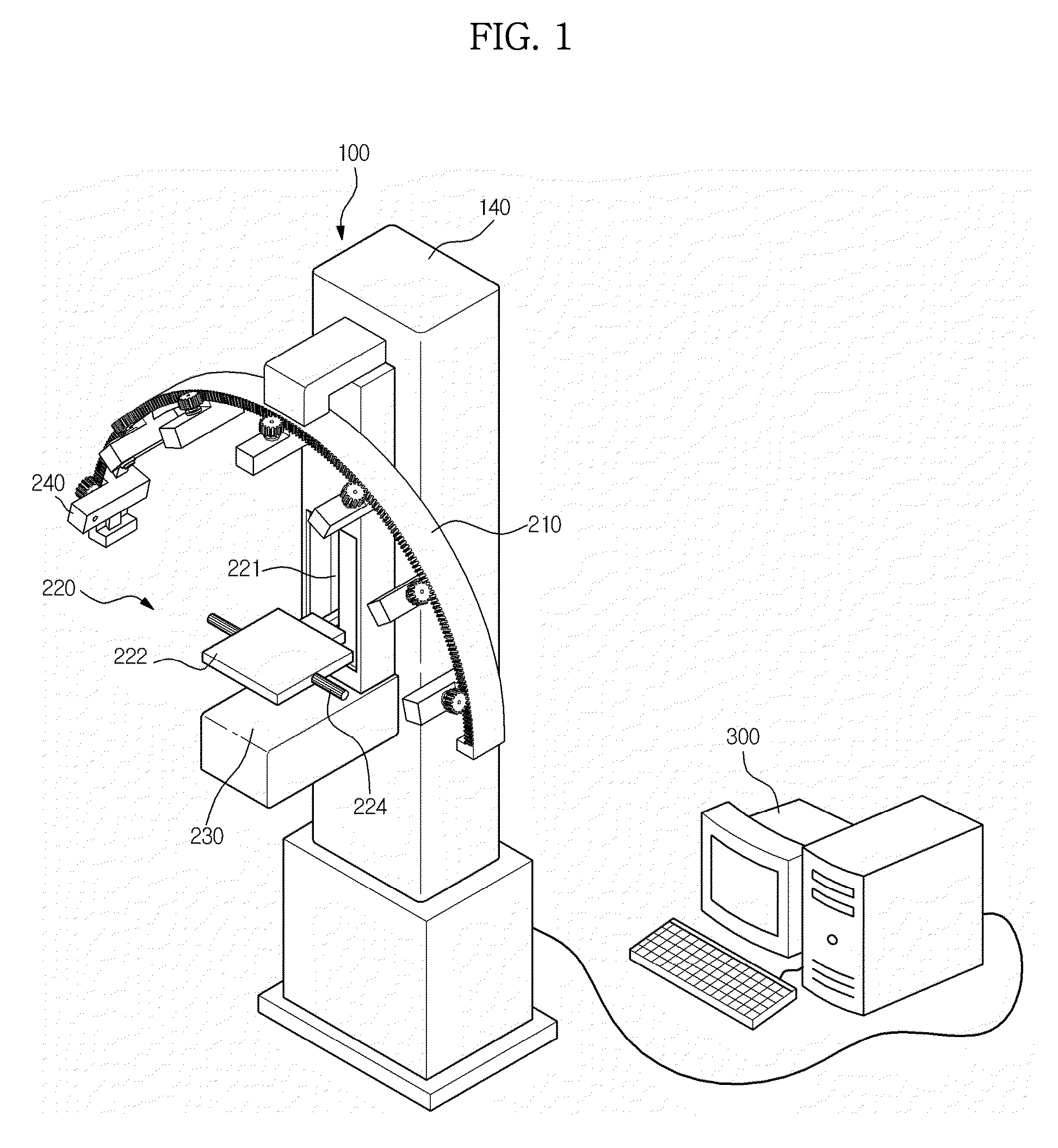
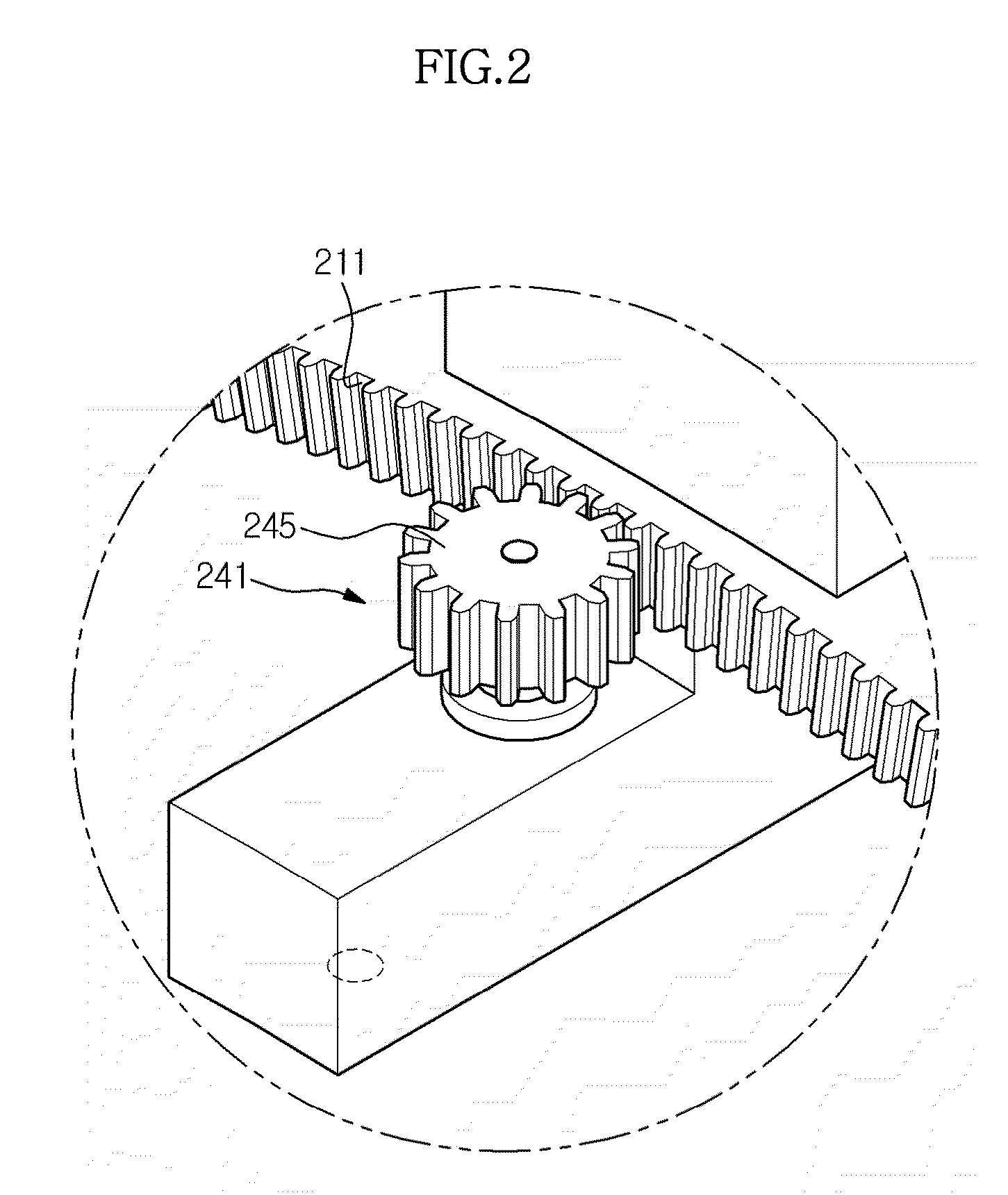
[0055]FIGS. 1 to 3 illustrate an X-ray imaging apparatus according to an exemplary embodiment.

[0056]Referring to FIGS. 1 to 3, the X-ray imaging apparatus includes a gantry 100 and an inspector workstation 300.

[0057]The gantry 100 includes a main body 140, a transfer member 210 secured to the main body 140, and a plurality of X-ray generation modules 240 configured to move a...


PUM


Abstract

Disclosed is an X-ray imaging apparatus, which includes a plurality of X-ray generation modules configured to emit X-rays to a subject, the X-ray generation modules being configured to move independently of one another, an X-ray detector configured to detect a plurality of X-rays emitted from the plurality of X-ray generation modules and which have passed through the subject, and an image processor configured to acquire a plurality of X-ray images from the plurality of detected X-rays.

Description

CROSS-REFERENCE TO RELATED APPLICATION[0001]This application claims the benefit of Korean Patent Application No. 10-2012-0116950, filed on Oct. 19, 2012 in the Korean Intellectual Property Office, the disclosure of which is incorporated herein by reference in its entirety.BACKGROUND[0002]1. Field[0003]Exemplary embodiments of the present disclosure relate to an X-ray generation module for generation and emission of X-rays, and an X-ray imaging apparatus and an X-ray imaging method which generate an X-ray image by transmitting X-rays through a subject and perform Automatic Exposure Control (AEC) using a plurality of X-ray generation modules.[0004]2. Description of the Related Art[0005]An X-ray imaging apparatus is an apparatus that diagnoses internal diseases of a subject by emitting X-rays to the subject and acquiring an image from X-rays having passed through the subject. X-ray imaging apparatuses which capture an image concentrated on an area of a human body have been marketed.[00...

Claims


Application Information

Patent Timeline
Patent Type & Authority Patents(United States)
IPC IPC(8): A61B6/04A61B6/00A61B6/03
CPCA61B6/502A61B6/03A61B6/488A61B6/542
Inventor JANG, KWANG EUNSUNG, YOUNG HUNLEE, JAE HAKLEE, JONG HA
Owner SAMSUNG ELECTRONICS CO LTD
Learn More