
Radiation image storage panel

a technology of image storage and fluorine resin, which is applied in the field of radioation image storage panels, can solve the problems of inability to achieve uniform image, and inability to form thin and uniform fluorine resin films, etc., and achieves good sharpness, low deterioration of image quality, and good sharpness.

Inactive Publication Date: 2005-07-14
FUJIFILM CORP +1
View PDF6 Cites 2 Cited by
  • Summary
  • Abstract
  • Description
  • Claims
  • Application Information

AI Technical Summary

Benefits of technology

[0012] The primary object of the present invention is to provide a radiation image storage panel, which has good water vapor proof characteristics and is capable of yielding an image of good image quality with a high sensitivity.
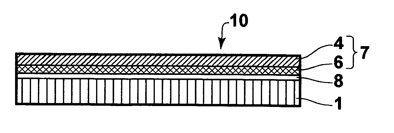
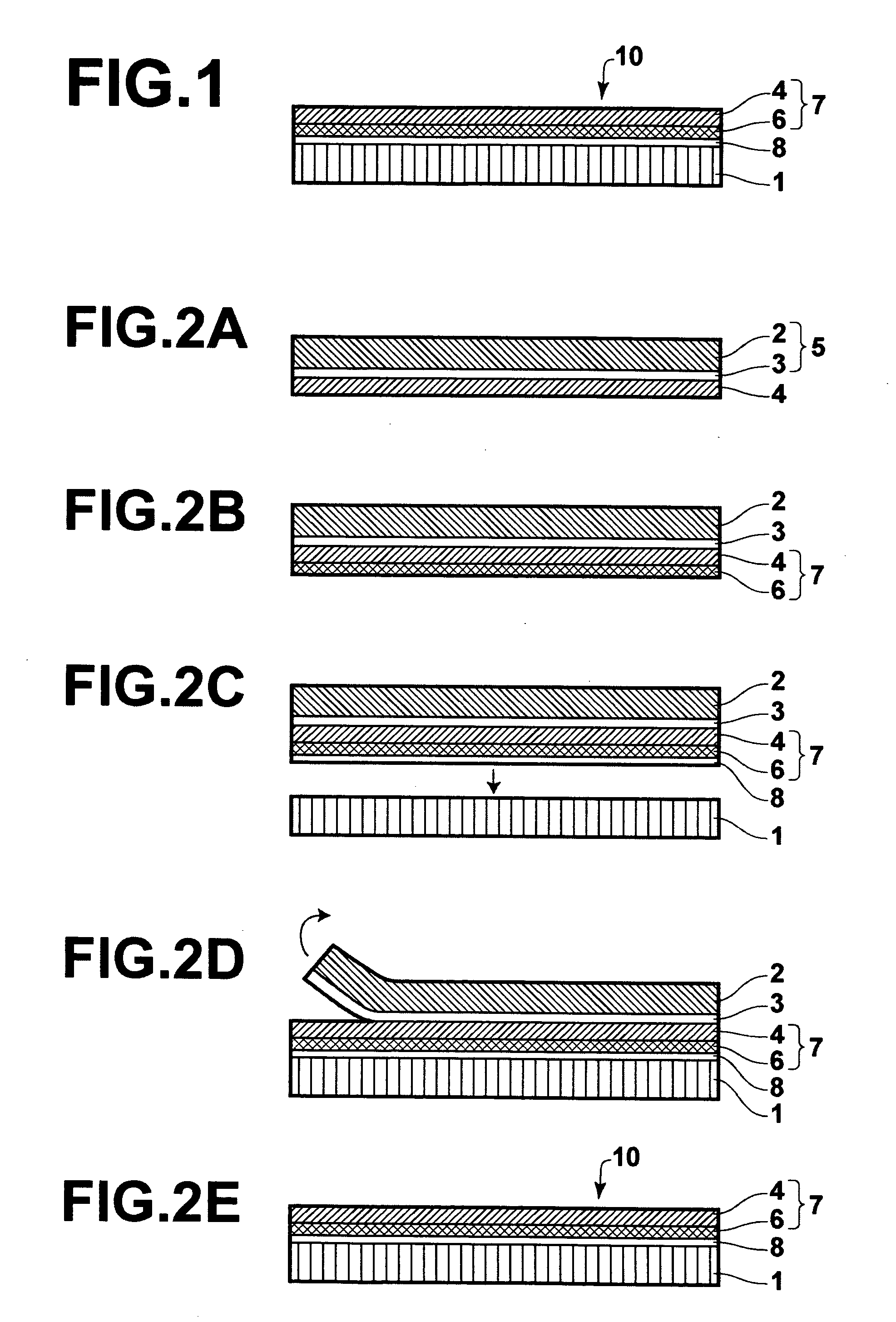
[0031] The radiation image storage panel in accordance with the present invention comprises the substrate, the stimulable phosphor layer, which is constituted of the stimulable phosphor, and the transparent water vapor proof film, which is constituted of the water vapor proof layer and the transparent thin film. The substrate, the stimulable phosphor layer, and the transparent water vapor proof film are overlaid in this order. The transparent water vapor proof film is overlaid via the adhesive layer on the stimulable phosphor layer. Also, the transparent thin film has a thickness falling within the range of 1 μm to 10 μm. Therefore, the radiation image storage panel in accordance with the present invention is capable of yielding an image having a good sharpness. Also, with the radiation image storage panel in accordance with the present invention, the water vapor proof layer prevents the stimulable phosphor from deteriorating due to absorption of water vapor. Accordingly, the radiation image storage panel in accordance with the present invention exhibits little deterioration in image quality during a long period of use.
[0032] Particularly, the radiation image storage panel in accordance with the present invention may be obtained with the process comprising the steps of: (a) laminating the transparent thin film and the peelable film with each other, the laminated film being thereby obtained, (b) overlaying the water vapor proof layer on the side of the transparent thin film of the laminated film, the transparent water vapor proof film, which is constituted of the transparent thin film and the water vapor proof layer, being thereby formed, (c) overlaying the transparent water vapor proof film on the stimulable phosphor layer via the adhesive layer, and (d) separating the peelable film from the transparent water vapor proof film. In such cases, the transparent thin film does not suffer from wrinkling. Also, by virtue of the use of the peelable film, even though the thickness of the transparent thin film is small, the water vapor proof layer is capable of being formed uniformly. Therefore, the radiation image storage panel in accordance with the present invention is capable of yielding an image having a high sharpness and good image quality and is capable of exhibiting good water vapor proof characteristics.
[0033] Also, the radiation image storage panel in accordance with the present invention should preferably be modified such that the transparent water vapor proof film has a water vapor transmission rate of at most 1 g / m2 / day. The radiation image storage panel in accordance with the present invention should more preferably be modified such that the transparent water vapor proof film has a water vapor transmission rate of at most 0.2 g / m2 / day. In such cases, the water vapor proof characteristics of the radiation image storage panel in accordance with the present invention are capable of being enhanced even further. Further, with the radiation image storage panel in accordance with the present invention, wherein the coating layer is formed on at least either one of the two surfaces of the water vapor proof layer, the water vapor proof characteristics of the radiation image storage panel are capable of being enhanced even further.
[0034] With the radiation image storage panel in accordance with the present invention, wherein the stimulable phosphor is a pillar-shaped crystal, the sharpness of the image obtained with the radiation image storage panel is capable of being enhanced even further. Also, with the radiation image storage panel in accordance with the present invention, wherein the stimulable phosphor is a pillar-shaped crystal, and wherein the adhesive layer has a layer thickness falling within the range of 0.3 μm to 2 μm, an image free from blurring is capable of being obtained.
[0035] With the radiation image storage panel in accordance with the present invention, wherein the radiation image storage panel further comprises the stimulating ray anti-reflection layer, in cases where energy of the stimulating rays is set to be high so as to enhance the sensitivity, the occurrence of interference of the stimulating rays is capable of being suppressed. Therefore, an image free from nonuniformity is capable of being obtained. Also, in cases where image readout from the radiation image storage panel in accordance with the present invention is performed by use of a line scanner, and the radiation image storage panel further comprises the emitted light anti-reflection layer, since intra-layer propagation of the light emitted by the stimulable phosphor is capable of being suppressed, the sharpness of the image obtained with the radiation image storage panel is capable of being enhanced even further.

Problems solved by technology

However, for technical and economical reasons, it is not always possible to form a thin and uniform fluorine resin film.
Therefore, with the radiation image storage panel disclosed in Japanese Unexamined Patent Publication No. 2001-141896, the problems are encountered in that image nonuniformity is apt to occur.
However, in cases where film forming is performed with the vacuum deposition technique on a protective layer substrate (a PET film) or an organic layer, on which the inorganic layer is to be formed, contraction and wrinkles occur with the film.
Therefore, an inorganic layer having sufficient water vapor proof performance is not capable of being obtained.
Also, the problems occur in that the image quality of the image obtained with the radiation image storage panel is adversely affected by the contraction and the wrinkles occurring with the film.
Further, with respect to a stimulable phosphor layer, which is constituted of pillar-shaped crystals and has a gap structure, it is not always possible to forma uniform inorganic evaporated layer.
However, the protective layer employed in the radiation image storage panel described in U.S. patent Laid-Open No. 20030038249 is apt to become thick.
Therefore, with the radiation image storage panel described in U.S. Patent Laid-Open No. 20030038249, the image quality of the obtained image will be apt to become bad.

Method used


Image

  • Radiation image storage panel
  • Radiation image storage panel

Examples


example 1

[0108] A soda-lime glass plate having a thickness of 8 mm, which had been subjected to washing with an alkali, washing with deionized water, and washing with isopropyl alcohol (IPA) in this order, was located as a substrate within a vacuum evaporation machine. Thereafter, CsBr and EuBr2 acting as deposition materials were filled respectively in predetermined resistance heating vessels. The distance between the substrate and each of the deposition materials was set at 0.15 m. Thereafter, the vacuum evaporation machine was evacuated to a degree of vacuum of 1×10⁻³Pa. An Ar gas was then introduced into the vacuum evaporation machine, and the degree of vacuum within the vacuum evaporation machine was thereby set at 1 Pa. The substrate was then heated to a temperature of 100° C. with a heater. Thereafter, each of the deposition materials was heated, and a CsBr:Eu stimulable phosphor was deposited on the surface of the substrate at a rate of 10 μm / min. At this time, the resistance current...

example 2

[0110] A radiation image storage panel was formed in the same manner as that in Example 1, except that the film thickness of the PET film was set at 6 μm.

example 3

[0111] A radiation image storage panel was formed in the same manner as that in Example 1, except that the film thickness of the PET film was set at 4.5 μm.


PUM

PropertyMeasurementUnit
thicknessaaaaaaaaaa
thicknessaaaaaaaaaa
thicknessaaaaaaaaaa

Abstract

A radiation image storage panel comprises a substrate, a stimulable phosphor layer, which is constituted of a stimulable phosphor, and a transparent water vapor proof film, which is constituted of a water vapor proof layer and a transparent thin film. The substrate, the stimulable phosphor layer, and the transparent water vapor proof film are overlaid in this order. The transparent water vapor proof film is overlaid via an adhesive layer on the stimulable phosphor layer. The transparent thin film has a thickness falling within the range of 1 μm to 10 μm. The radiation image storage panel has good water vapor proof characteristics and is capable of yielding an image of good image quality with a high sensitivity.

Description

BACKGROUND OF THE INVENTION [0001] 1. Field of the Invention [0002] This invention relates to a radiation image storage panel for use in radiation image recording and reproducing techniques utilizing stimulable phosphors. [0003] 2. Description of the Related Art [0004] Radiation image recording and reproducing systems utilizing stimulable phosphors have heretofore been known as computed radiography (CR). The radiation image recording and reproducing systems utilizing the stimulable phosphors comprise a radiation image recording apparatus for irradiating radiation carrying image information of an object, such as a human body, and storing a radiation image of the object as a latent image on a layer of the stimulable phosphor. The radiation image recording and reproducing systems utilizing the stimulable phosphors also comprise a radiation image read-out apparatus for exposing the stimulable phosphor layer, on which the latent image of the radiation image has been stored, to stimulatin...

Claims


Application Information

Patent Timeline
Patent Type & Authority Applications(United States)
IPC IPC(8): G21K4/00C09K11/00C09K11/77G01T1/00G03B42/02G03C5/16
CPCG21K4/00C09K11/7733
Inventor TAKASU, ATSUNORITAZAKI, SEIJIKIDO, TAKEO
Owner FUJIFILM CORP
Learn More